EasyManua.ls Logo

JVC HR-S2901U User Manual

JVC HR-S2901U
77 pages
To Next Page IconTo Next Page
To Previous Page IconTo Previous Page
Page #27 background imageLoading...
Page #27 background image
1-10
Tape transport
Drum assembly
A/C head
Pinch roller arm assembly
Full erase head
Tension arm assembly
Capstan motor (Shaft)
Guide arm assembly
Capstan motor
Capstan brake assembly
Main brake assembly
Belt (Capstan)
Loading motor
Clutch unit
Worm gear
Control plate
Rotary encoder
C,X
C,X
C
C
C
C
C
X
X
C,X
C
C
C
C
C
X
X
X
X
X
X
X
X
X
Operation hours
1000H
2000H
Drive
System Parts name
C : Cleaning
X : Inspection or Replacement if necessary
Other
1.7 Maintenance and inspection
1.7.1 Cleaning
Regular cleaning of the transport system parts is desirable but
practically impossible. So make it a rule to carry out cleaning
of the tape transport system whenever the machine is serv-
iced.
When the video head, tape guide and/or brush get soiled, the
playback picture may appear inferior or at worst disappear, re-
sulting in possible tape damage.
Note:
Absolutely avoid sweeping the upper drum vertically as
this will cause damage to the video head.
(1) When cleaning the upper drum (especially the video head),
soak a piece of closely woven cloth with alcohol and while
holding the cloth onto the upper drum by the fingers, turn
the upper drum counterclockwise.
(2) To clean the parts of the tape transport system other than
the upper drum, use a piece of closely woven cloth or a
cotton swab soaked with alcohol.
(3) After cleaning, make sure that the cleaned parts are com-
pletely dry before using the cassette tape.
Fig. 1-7-1a
1.7.2 Lubrication
With no need for periodical lubrication, you have only to lubri-
cate new parts after replacement. If any oil or grease on con-
tact parts is soiled, wipe it off and newly lubricate the parts.
Note:
See the “mechanism assembly” diagram of the “parts list”
for the lubricating or greasing spots, and for the types of
oil or grease to be used.
1.7.3 Suggested servicing schedule for main components
The following table indicates the suggested period for such
service measures as cleaning, lubrication and replacement. In
practice, the indicated periods will vary widely according to en-
vironmental and usage conditions. However, the indicated com-
ponents should be inspected when a set is brought for service
and the maintenance work performed if necessary. Also note
that rubber parts may deform in time, even if the set is not used.
Video heads
A/C head

Table of Contents

Question and Answer IconNeed help?

Do you have a question about the JVC HR-S2901U and is the answer not in the manual?

JVC HR-S2901U Specifications

General IconGeneral
BrandJVC
ModelHR-S2901U
CategoryVCR
LanguageEnglish

Summary

SPECIFICATIONS

General Specifications

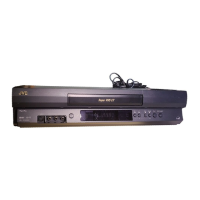
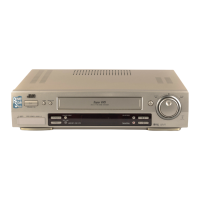
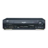
Details general operational and physical characteristics, power requirements, dimensions, and format.

Tuner Specifications

Information on the tuning system, channel coverage, and RF output.

Timer Specifications

Details on clock reference and program capacity for the timer function.

Provided Accessories

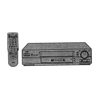
Lists accessories provided with the VCR unit.

IMPORTANT SAFETY PRECAUTIONS

Servicing Safety Precautions

Crucial guidelines for safe service procedures, component replacement, and handling electrical hazards.

INSTRUCTIONS

Disassembly Procedures

Step-by-step guide for disassembling the VCR, including manual cassette removal.

MECHANISM

Mechanism Pre-Disassembly Checks

Notes and checks required before disassembling the mechanism assembly.

Mechanism Parts Replacement

Detailed procedures for removing and installing key mechanism components.

Mechanism Timing Chart

Diagram illustrating the timing sequence of mechanism operations during playback modes.

ADJUSTMENT

Pre-Adjustment Procedures

Essential precautions, required equipment, and initial setup for adjustments.

Mechanism Compatibility Adjustment

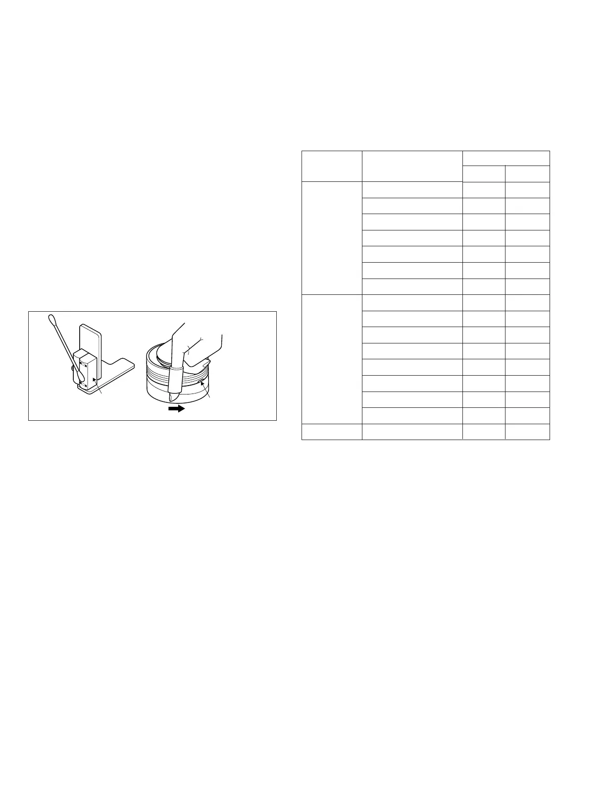
Procedures for adjusting mechanism components like tension pole and A/C head alignment.

Electrical Adjustment Procedures

Steps for adjusting servo, video, and audio circuits for optimal performance.

CHARTS AND DIAGRAMS

Schematic Diagram Notes

Important notes on component units, voltage indications, and connector symbols in schematics.

Board Interconnections Diagram

Diagram showing connections between major circuit boards and external connectors.

Main Video/Audio Schematic

Schematic diagram detailing the video and audio processing circuits.

Remote Controller Schematic Diagram

Schematic diagram for the remote controller unit.

Signal Waveforms

Illustrations of expected waveforms at various test points during operation.

CPU Pin Function Details

Description of pin functions for the System Control Microcomputer (IC3001).

System Control Block Diagram

Block diagram illustrating the system control logic and signal flow.

PARTS LIST

Packing and Accessory Parts List

List of parts included in the packing and accessory assembly.

Final Assembly Parts List

List of parts pertaining to the final assembly of the VCR unit.

Mechanism Assembly Parts List

List of parts constituting the mechanism assembly of the VCR.

Electrical Parts List

List of electrical components used across various circuit boards.

Related product manuals