2-9
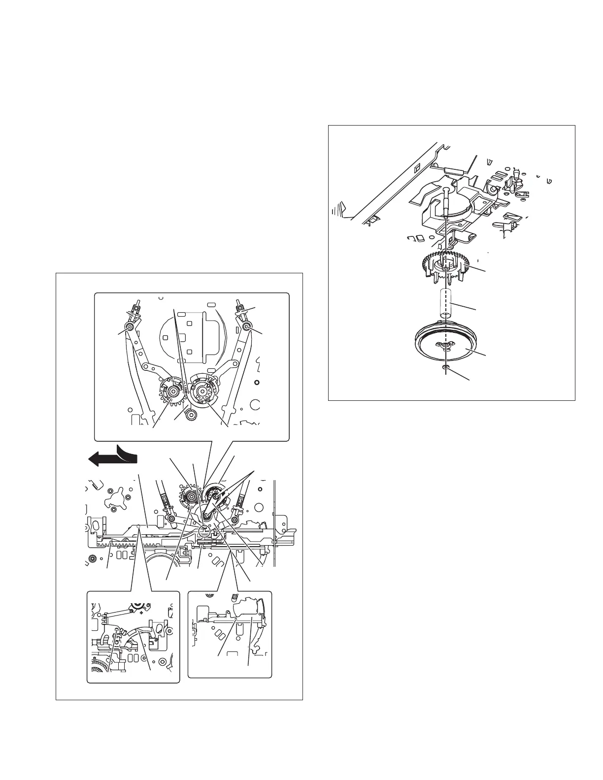
2.2.7.2 Installation (phase adjustment)
(1) Place the main deck on the guide hole (a) of the tension arm
lever.
(2) Place the main deck on the guide hole (b) of the brake le-
ver.
(3) Attach the control plate to align with the position guide (a).
(4) Place the hole (c) of the load arm (T) on the pole base (T)
and the load gear (T) on the load gear base.
(5) Place the hole (d) of the load arm (S) on the pole base (S)
and the load gear (S) on the load gear base. Be sure to align
the guide mark (e) of the load gear (T) to that of the load
gear (S).
(6) Turn the load gear (S/T) in the unloading direction to place
the main deck on the guide hole (f) of the load gear (T).
(7) Place the main deck on the guide hole (g) of the control plate.
(8) Attach the load gear on the load gear base so that the con-
trol plate is placed on the edge (h) of the load gear.
(9) Place the fixing plate on the shaft of the load gear base and
secure the screws (b).
Fig. 2-2-7b
2.2.8 Clutch unit assembly, direct gear
2.2.8.1 Removal
(1) Remove the slit washer (a) to detach the clutch unit assem-
bly.
(2) Remove the spring (a) and the direct gear.
Fig. 2-2-8a
Guide marks (e)
Load gear (T) assembly
LOAD GEAR BASE
Hole (d)
POLE
BASE(S)
Hole (c)
POLE
BASE(T)
Load gear (S) assembly
Guide hole (f)
Guide hole (g)
Position guide (a)
LOAD GEAR
FIXING
PLATE
Load gear (S)
assembly
Screws (b)
Load gear (T)
assembly
CONTROL PLATE
Guide hole (a)
TENSION ARM LEVER
Guide hole (b)
BRAKE LEVER
(From the top)
Edge (h)
Insertion direction
DIRECT GEAR
Spring (a)
CLUTCH UNIT
Slit washer (a)
 Loading...