KS-AX6700
1-5
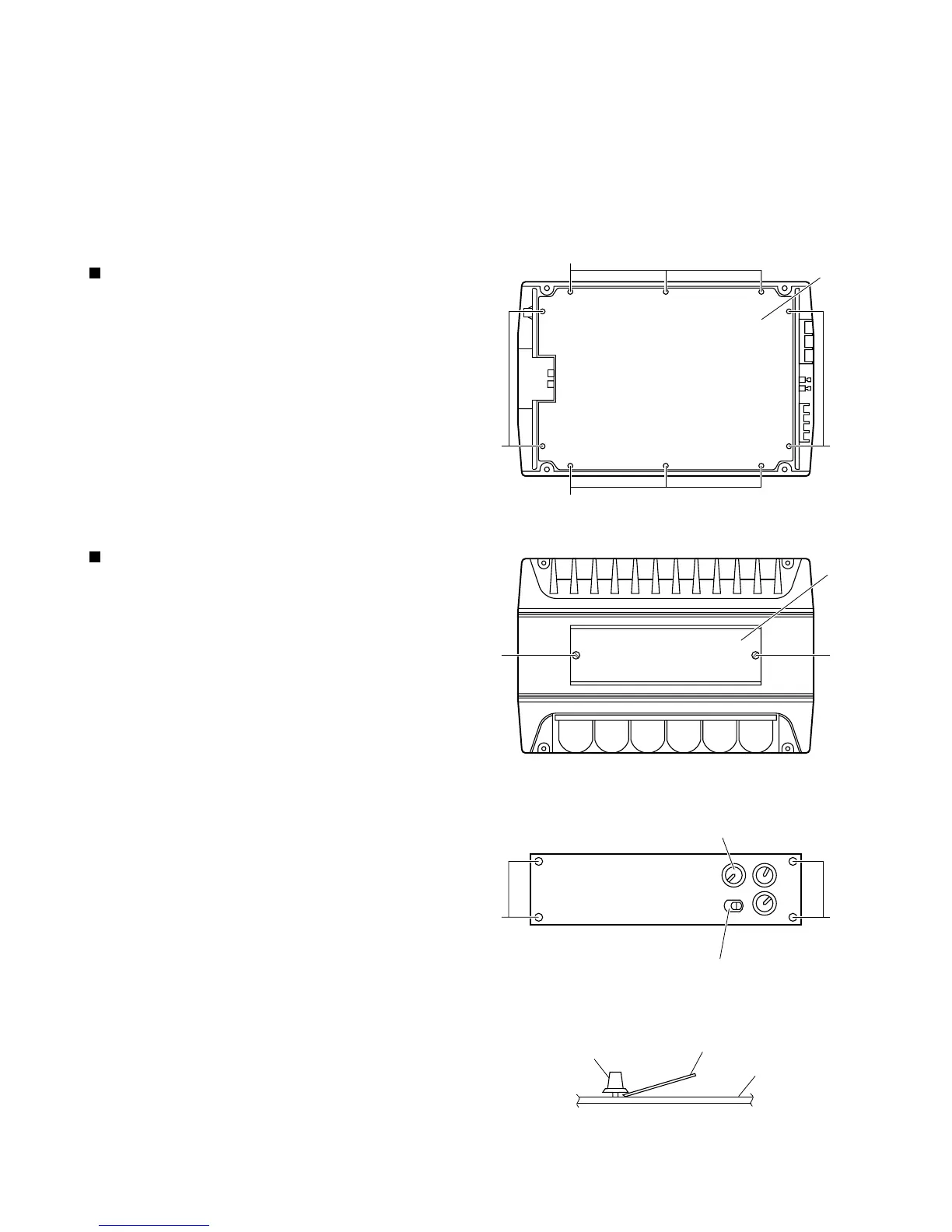
From the bottom side of the main unit, remove the 4
screws A retaining the bottom cover.
Then remove the 6 screws B retaining the bottom
cover.
Remove the bottom cover.
1.
2.
3.
If electricity is connected during
disassembly, it must be a no load current. If
it is load current, be sure to attach a heat
sink to the power-amp IC. This will be
damaged if the above precautions are not
followed, as it does not have a sub heat
sink attached to it.
CAUTION:
Removal of main parts
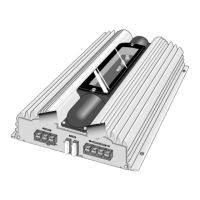
Removing the bottom cover (see Fig. 1)
Remove the bottom cover from the main unit.
Loosen and remove the 2 screws C retaining the top
plate on the main unit. (Stoppers are attached to the
backs of the C screws so that they cannot be
removed easily.)
1.
2.
Remove the 3 volume knobs on top of the control
panel. If it cannot be pulled out easily, insert a scale
or suitable lever between the base of the volume
knob and the control panel so that the volume knob is
raised a little above the surface and then remove it.
(Be careful when inserting a lever etc. not to
scratch the surface of the control panel).
Remove the 4 screws D retaining the control panel.
Then detach the control panel and the switch knob.
3.
4.
Removing the main P.C. board
(see Fig. 2 to 8)
(Side view)
Scale or suitable lever
D
Top plate
C
Volume knob
Control panel
Bottom cover
B
Fig. 1
Fig. 3
Fig. 2
Fig. 4
A
D
C
A
B
Volume knob
Switch knob
 Loading...