1-8 (No.YA711<Rev.002>)
SECTION 3
DISASSEMBLY
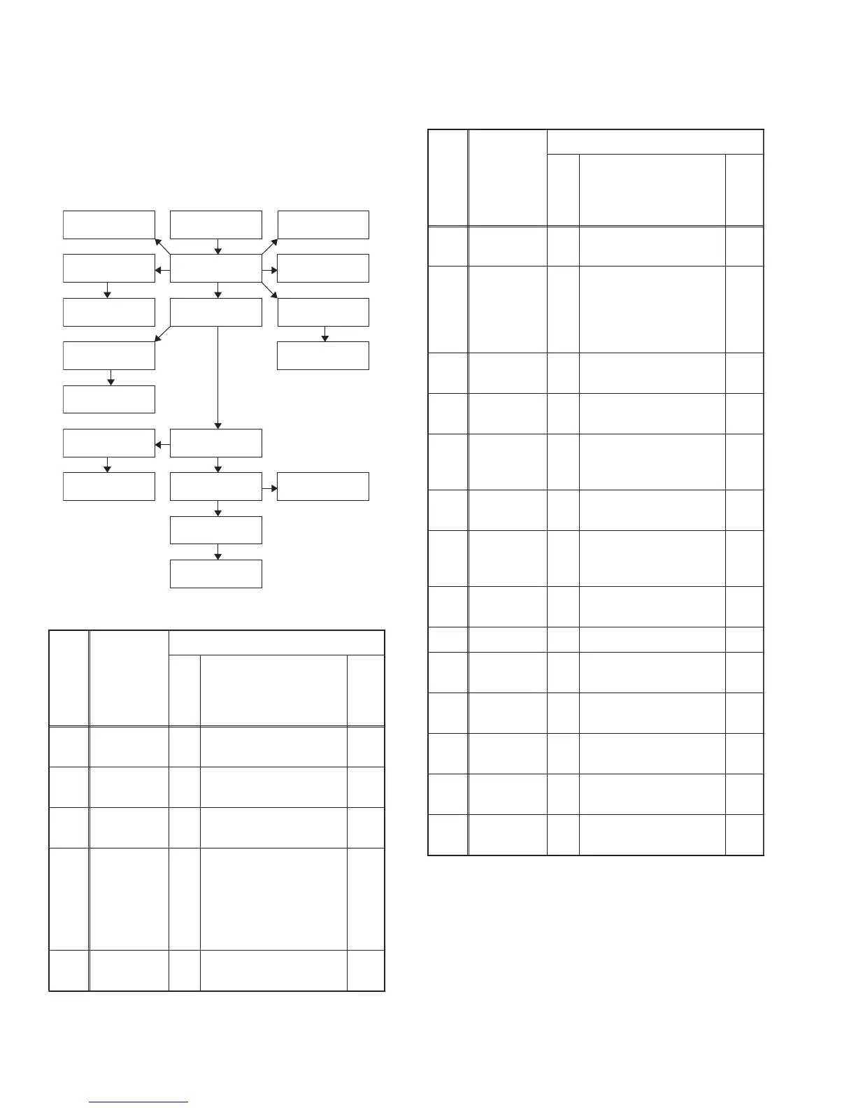
3.1 DISASSEMBLY FLOWCHART
This flowchart indicates the disassembly steps for the cabinet
parts, and the PWB in order to gain access to item(s) to be ser-
viced. When reassembling, follow the steps in reverse order.
Bend, route and dress the cables as they were.
3.2 DISASSEMBLY METHOD
[1] Stand
Assembly
[4] DVD
Mechanism
[5] DVD Main
PWB Unit
[2] Rear Cabinet
[16] Junction-B
PWB
[6] Jack Holder
(D)
[15] Junction-C
PWB
[10] Main PWB
[13] Speaker
Holder (s)
[9] Jack PWB
[14] Speaker (s)
[3] DVD Holder
[11] Stand Holder
[7] Digital Main
PWB Unit
[18] Function
PWB
[12] LCD Module
Assembly
[19] Front
Cabinet
[8] Jack Holder
(A)
[17] Junction-A
PWB
Step/
Loc.
No.
Part
Removal
Fig.
No.
Remove/*Unhook/
Unlock/Release/
Unplug/Unclamp/
Desolder
Note
[1]
Stand
Assembly
D1 3(S-1) ---
[2]
Rear
Cabinet
D1 10(S-2), 2(S-3), (S-4) ---
[3] DVD Holder
D2
D5
4(S-5), 3(S-6),
*CN901, *CN902
---
[4]
DVD
Mechanism
D2
D5
(S-7), *CN201,
*CN301, *CN801
1
2
3
4
5
6
[5]
DVD Main
PWB Unit
D2 --------------- ---
[6]
Jack
Holder(D)
D3 (S-8) ---
[7]
Digital Main
PWB Unit
D3
D5
4(S-9), (S-10),
4(S-11), 2(H-1),
*CN301, *CN302,
*CN303, *CN3902,
Shield Box
---
[8]
Jack
Holder(A)
D3 (S-12) ---
[9] Jack PWB
D3
D5
4(S-13), CN702,
*CN861A
---
[10] Main PWB
D3
D5
7(S-14), *CN102,
*CN201, *CN862A,
*CN1001, *CN1002
---
[11]
Stand
Holder
D4 2(S-15), (S-16) ---
[12]
LCD
Module
Assembly
D4 --------------- ---
[13]
Speaker
Holder(s)
D4 4(S-17) ---
[14] Speaker(s) D4 --------------- ---
[15]
Junction-C
PWB
D4
D5
Desolder ---
[16]
Junction-B
PWB
D4
D5
Desolder ---
[17]
Junction-A
PWB
D4
D5
Desolder ---
[18]
Function
PWB
D4
D5
2(S-18) ---
[19]
Front
Cabinet
D4 --------------- ---
(1) (2) (3) (4) (5)
Step/
Loc.
No.
Part
Removal
Fig.
No.
Remove/*Unhook/
Unlock/Release/
Unplug/Unclamp/
Desolder
Note
 Loading...