1-2 (No.PA063<Rev.001>)
SECTION 1
PRECAUTION
1.1 SAFETY PRECAUTIONS
Prior to shipment from the factory, JVC products are strictly in-
spected to conform with the recognized product safety and elec-
trical codes of the countries in which they are to be
sold.However,in order to maintain such compliance, it is equally
important to implement the following precautions when a set is
being serviced.
1.1.1 PRECAUTIONS DURING SERVICING
(1) Locations requiring special caution are denoted by labels
and inscriptions on the cabinet, chassis and certain parts of
the product.When performing service, be sure to read and
comply with these and other cautionary notices appearing
in the operation and service manuals.
(2) Parts identified by the symbol and shaded ( ) parts
are critical for safety.
Replace only with specified part numbers.
NOTE :
Parts in this category also include those specified to
comply with X-ray emission standards for products
using cathode ray tubes and those specified for
compliance with various regulations regarding spu-
rious radiation emission.
(3) Fuse replacement caution notice.
Caution for continued protection against fire hazard.
Replace only with same type and rated fuse(s) as speci-
fied.
(4) Use specified internal wiring. Note especially:
• Wires covered with PVC tubing
• Double insulated wires
• High voltage leads
(5) Use specified insulating materials for hazardous live parts.
Note especially:
• Insulation Tape
• PVC tubing
• Spacers
• Insulation sheets for transistors
• Barrier
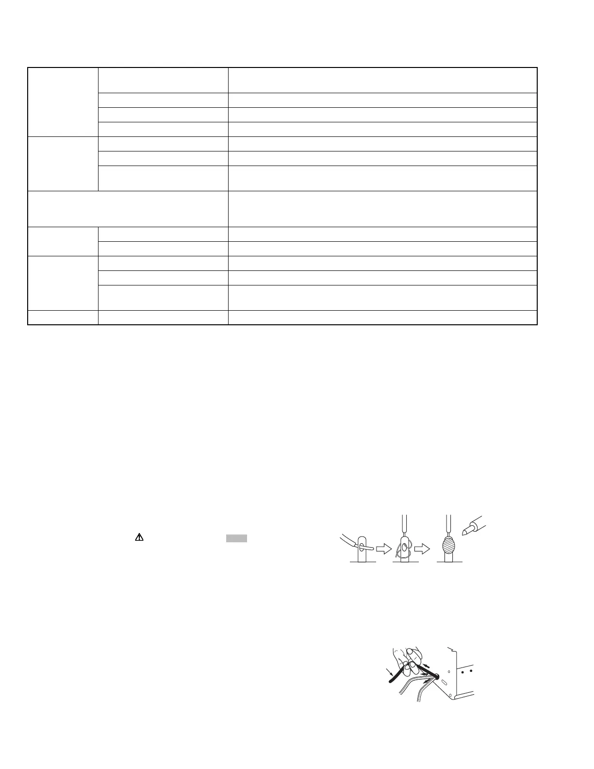
(6) When replacing AC primary side components (transformers,
power cords, noise blocking capacitors, etc.) wrap ends of
wires securely about the terminals before soldering.
Fig.1-1-1
(7) Observe that wires do not contact heat producing parts
(heat sinks, oxide metal film resistors, fusible resistors,
etc.)
(8) Check that replaced wires do not contact sharp edged or
pointed parts.
(9) When a power cord has been replaced, check that 10-15
kg of force in any direction will not loosen it.
Fig.1-1-2
(10) Also check areas surrounding repaired locations.
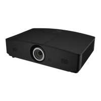
Optical Resolution 1920 x 1080
3840 x 2160 with e-shift
Display system Single-chip DLP™ system
Lens F = 1.809, f = 14.3 to 22.9 mm
Lamp Laser
Electrical Power supply AC100 to 240V, 3.7 A, 50/60 Hz (Automatic)
Power consumption 360 W (Max); < 0.5 W (Standby);
Output terminals 12VDC (Max. 0.1 A) x 1
DC 5V output (Max. 1.5 A) x 1
Control RS-232 serial control: 9 pin x 1
IR receiver x 2
USB Mini-B x 1
Input terminals Computer input RGB input: D-Sub 15-pin (female) x 1
Video signal input SD/HDTV signal input: Digital - HDMI x 2
Environmental
Requirements
Operating temperature 0C to 40C at sea level
Operating relative humidity 10% to 90% (without condensation)
Operating altitude 0 to 1499 m at 0C to 35C
1500 to 3000 m at 0C to 30C (with High Altitude Mode on)
Mechanical Weight 6.3 Kg (13.89 lbs)
Power cord
 Loading...