1-4 (No.PA063<Rev.001>)
(5) Grounding (Class 1 model only)
Confirm specified or lower grounding impedance between
earth pin in AC inlet and externally exposed accessible
parts (Video in, Video out, Audio in, Audio out or Fixing
screw etc.).Measuring Method:
Connect milli ohm meter between earth pin in AC inlet and
exposed accessible parts. See Fig.1-1-10 and grounding
specifications.
Fig.1-1-10
Fig.1-1-11
Fig.1-1-12
NOTE:
These tables are unofficial and for reference only. Be sure to confirm the precise values for your particular country and locality.
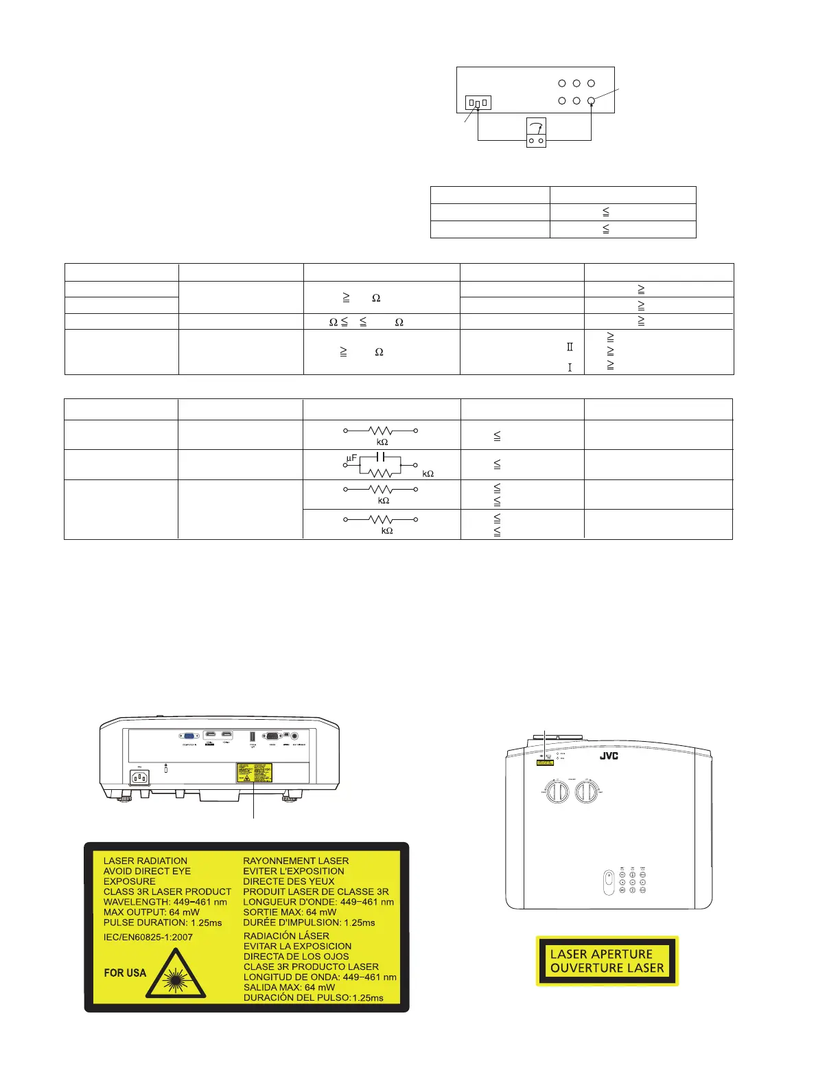
1.2 WARNING AND CAUTION LABELS
1.2.1 FOR THE CUSTOMERS IN THE U.S.A. AND CANADA
• Use the controls or adjustments or performance of procedures
other than those specified herein may result in hazardous ra-
diation exposure.
• This Projector is classified as a CLASS 3R LASER PRODUCT.
• This CLASS 3R LASER
Exposed accessible part
Grounding Specifications
AC inlet
Region
USA & Canada
Europe & Australia
Grounding Impedance
(
Z
)
Z 0.1 ohm
Z 0.5 ohm
Earth pin
MIlli ohm meter
AC Line Voltage
Region
Japan
Europe & Australia
R 1 M /500 V DC
USA & Canada
1 M R 12 M /500 V DC
R 10 M /500 V DC
Insulation Resistance
(
R
)
Dielectric Strength
Clearance Distance
(
d
)
,
(
d'
)
100 V
100 to 240 V
110 to 130 V
110 to 130 V
200 to 240 V
AC 1 kV 1 minute
AC 1.5 kV 1 minute
AC 1 kV 1 minute
(
Class
)
(
Class
)
AC 3 kV 1 minute
AC 1.5 kV 1 minute
d, d' 3 mm
d, d' 4 mm
d, d' 3.2 mm
d' 8 m m
(
Power cord
)
d' 6 m m
(
Primary wire
)
d 4 m m
AC Line Voltage
Region
Japan
Europe & Australia
USA & Canada
Load Z
Leakage Current (i)
a, b, c
100 V
110 to 130 V
110 to 130 V
220 to 240 V
i 1 mA rms
i 0.5 mA rms
i 0.7 mA peak
i 2 mA dc
i 0.7 mA peak
i 2 mA dc
Exposed accessible parts
Exposed accessible parts
Antenna earth terminals
Other terminals
1
1.5
2
50
0.15
LASER CAUTION LABEL
(LASER CAUTION LABEL)
APERTURE LABEL
(APERTURE LABEL)
 Loading...