(No.MB421)1-11
3.1.7 Removing the power board
(See Figs.12 and 13)
• Prior to performing the following procedures, remove the metal
cover.
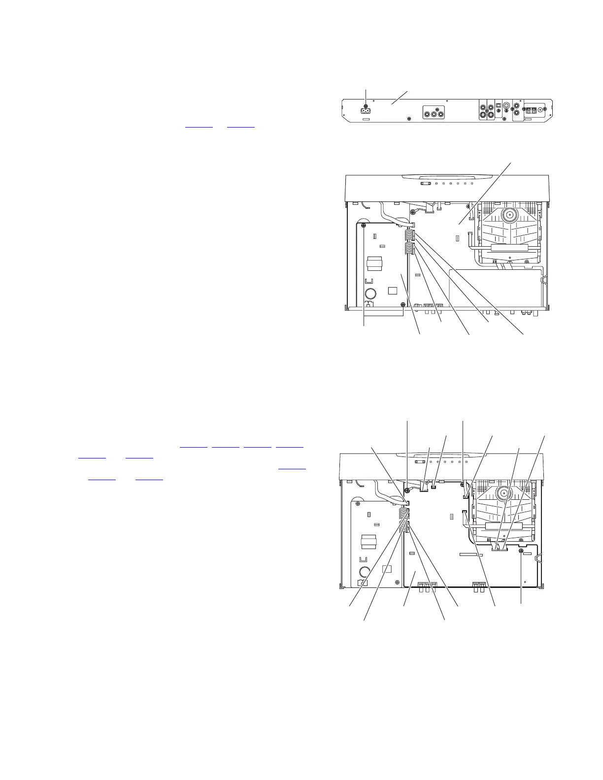
(1) From the back side of the main body, remove the screw K
attaching the power board to the rear panel. (See Fig.12)
(2) From the top side of the main body, disconnect the parallel
wires from the connectors CN404
to CN407 on the main
board. (See Fig.13)
(3) Remove the two screws M attaching the power board. (See
Fig.13)
(4) Release the holder using a pliers and take out the trans-
former board from the main body.
Reference:
Remove the rear panel as required. (See "3.1.3 Removing the
rear panel")
Fig.12
Fig.13
3.1.8 Removing the main board
(See Fig.14)
• Prior to performing the following procedures, remove the metal
cover, rear panel, audio signal input/output board and tuner as-
sembly.
(1) From the top side of the main body, disconnect the card
wires from the connectors CN401
, CN402, CN408, CN451,
CN452 and CN460 on the main board.
(2) Disconnect the parallel wires from the connectors CN404
to CN407 and CN420 on the main board.
(3) From the top side of the main body, remove the two screws
N, screw N' attaching the main board on the main body.
(4) Take out the main board from the main body.
Reference:
When attaching the screw N', attach the earth wire with it. (See
Fig.14)
Fig.14
K
Rear panel
CN404 CN406
CN405 CN407
Main board
Power board
M
N
N
CN404
CN451
CN460
CN406
CN405CN407
CN420
CN402
CN401
CN452
Main board
N'
CN408
 Loading...