1-12 (No.MB421)
3.2 Front panel assembly section
• Prior to performing the following procedures, remove the metal cover and front panel assembly.
3.2.1 Removing the HP board
(See Fig.1)
(1) From the inside of the front panel assembly, remove the
two screws A attaching the HP board.
(2) Take out the HP board from the front panel assembly.
3.2.2 Removing the KEY and LED board
(See Fig.1 and 2)
• Prior to performing the following procedures, remove the metal
cover and front panel assembly.
(1) From the inside of the front panel assembly, remove the
three screws B attaching the KEY board.(See Fig.1)
(2) Take out the KEY and LED board from the front panel as-
sembly. (See Fig.1)
Reference:
When attaching the KEY and LED board, make sure parallel
wire in the KEY board slot.
(See Fig.1)
When attaching the LED board, slot in the LED board into claw
of front panel assembly and push to the arrow direction. (See
Fig. 2)
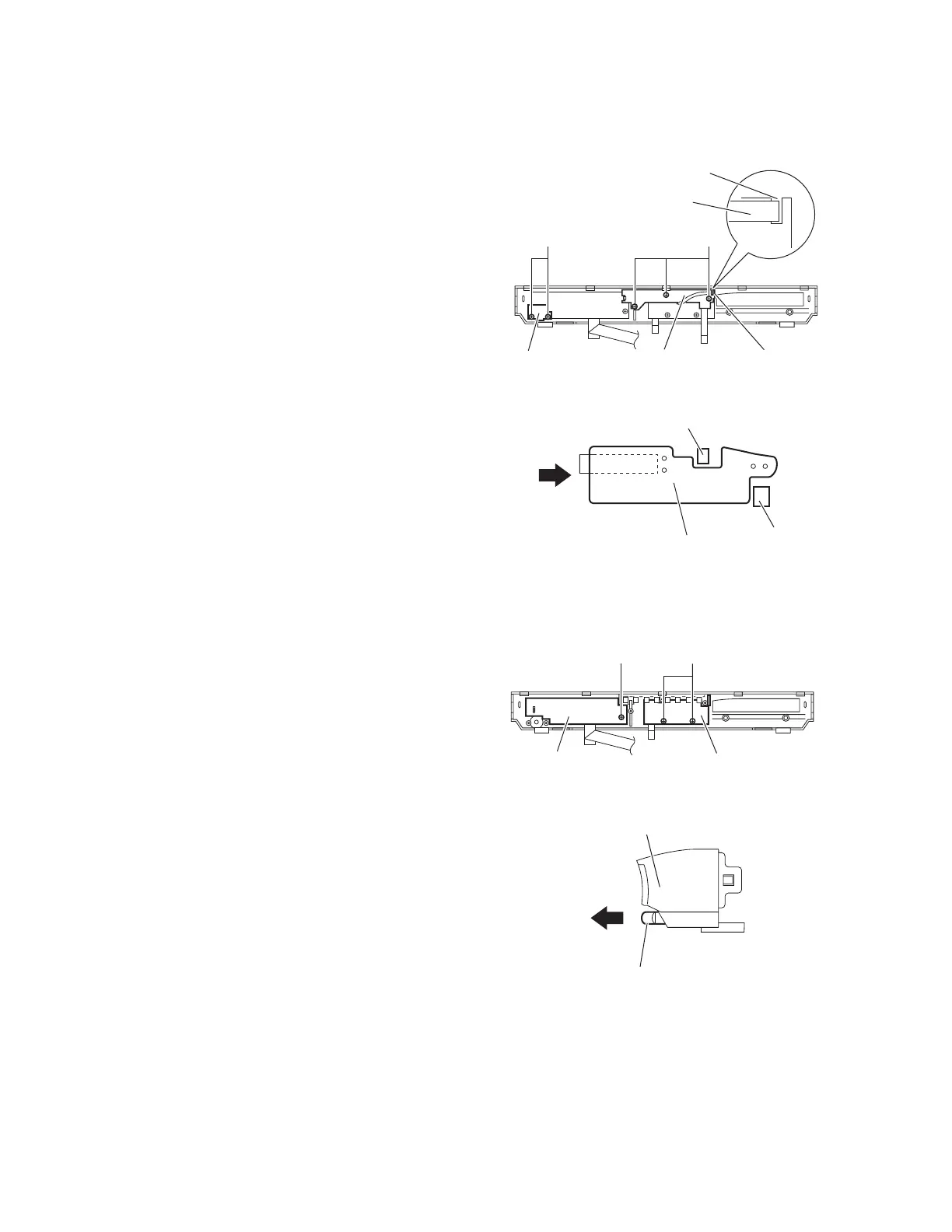
Fig.1
Fig.2
3.2.3 Removing the FL board
(See Fig.3)
• Prior to performing the following procedures, remove the metal
cover and front panel assembly.
(1) From the inside of the front panel assembly, remove the
screw C attaching the FL board.
(2) Take out the FL board from the front panel assembly.
3.2.4 Removing the MIC board
(See Fig.3 and 4)
• Prior to performing the following procedures, remove the metal
cover , front panel assembly , KEY board and LED board.
(1) From the front side of the front panel assembly, pull out the
volume knob in the direction of the arrow. (See Fig. 4)
(2) From the inside of the front panel assembly, remove the
two screws D attaching the MIC board. (See Fig. 3)
(3) Take out the MIC board from the front panel assembly.
(See Fig. 3)
Fig.3
Fig.4
B
HP board
Slot
KEY board
LED board
A
Parallel wire
LED board
Claw
Claw
D
FL board MIC board
C
Volume knob
Front panel assembly
 Loading...