If you need more detailed information, see page 6.
TV
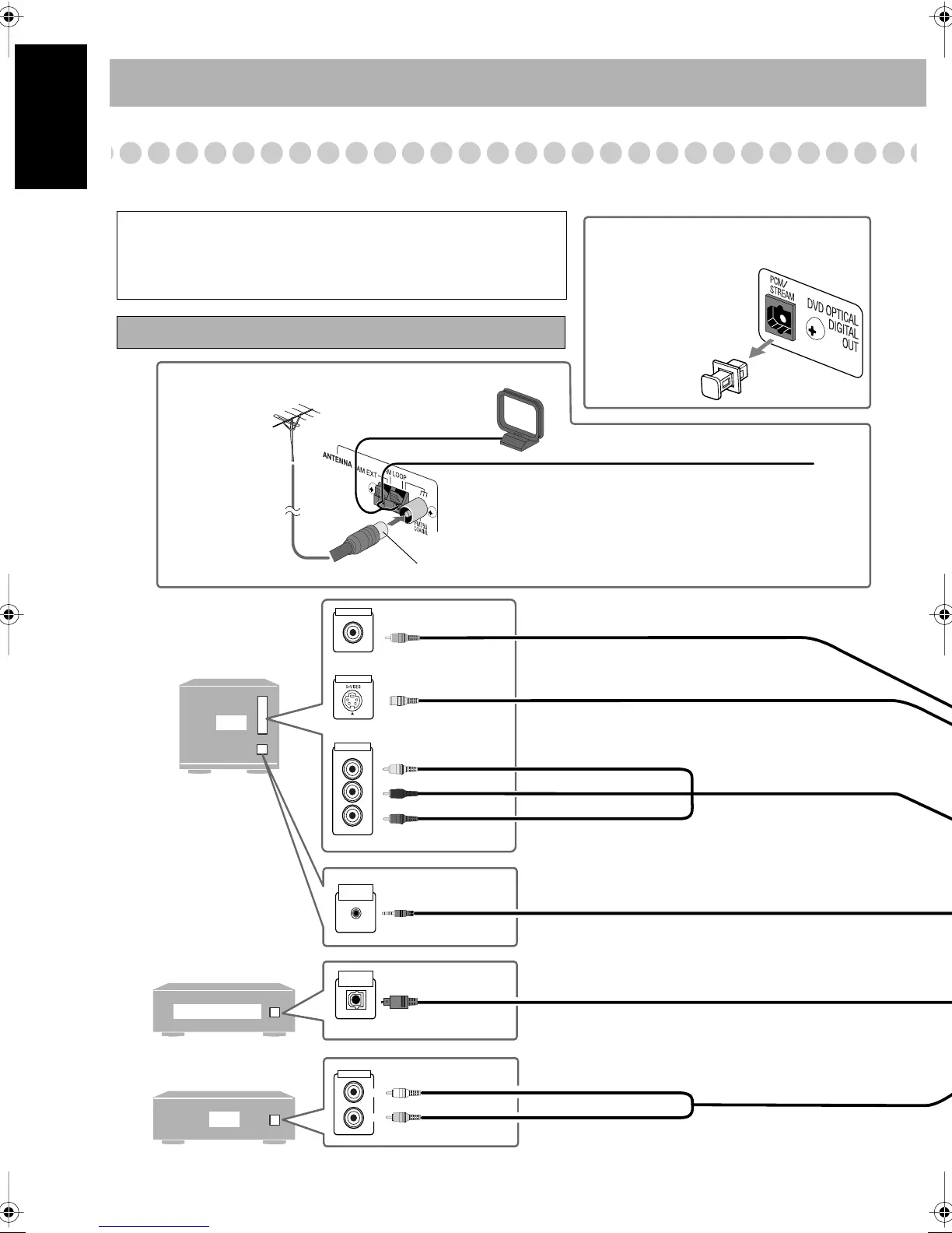
AUX
DECODER
LEFT
RIGHT
AUDIO OUT
OPTICAL
DIGITAL IN
AV
COMPU LINK
VIDEO INPUT
VIDEO INPUT
VIDEO INPUT
Y
P
B
P
R
Illustrations of the input/output terminals below are typical
examples.
When you connect other components, refer also to their manuals
since the terminal names actually printed on the rear may vary.
Turn the power off to all components before connections.
Audio cord (not supplied)
White
Red
Optical digital cord (not supplied)
Component video cord (not supplied)
Red
Blue
Green
AV COMPU LINK cord (not supplied)
(cord with monaural mini plug)
• For details, see “AV COMPU LINK remote control
system” on page 6.
Before connecting optical digital
cord
OR
S-video cord (not supplied)
Composite video cord (supplied)
Yellow
OR
VCR, etc.
Remove the protective
cap from the DVD
OPTICAL DIGITAL
OUT terminal.
Vinyl-covered wire (not supplied)
Extend it horizontally.
For better FM/AM reception
AM loop antenna
Keep it connected.
Disconnect the supplied FM antenna, and connect to an outdoor FM
antenna using a 75 Ω wire with coaxial type connector.
Outdoor FM
antenna
(not supplied)

 Loading...


