Page 10 Operating Instructions Powador 2500xi / 3600xi / 4000xi / 4500xi / 5000xi_EN
4.6 DC disconnector
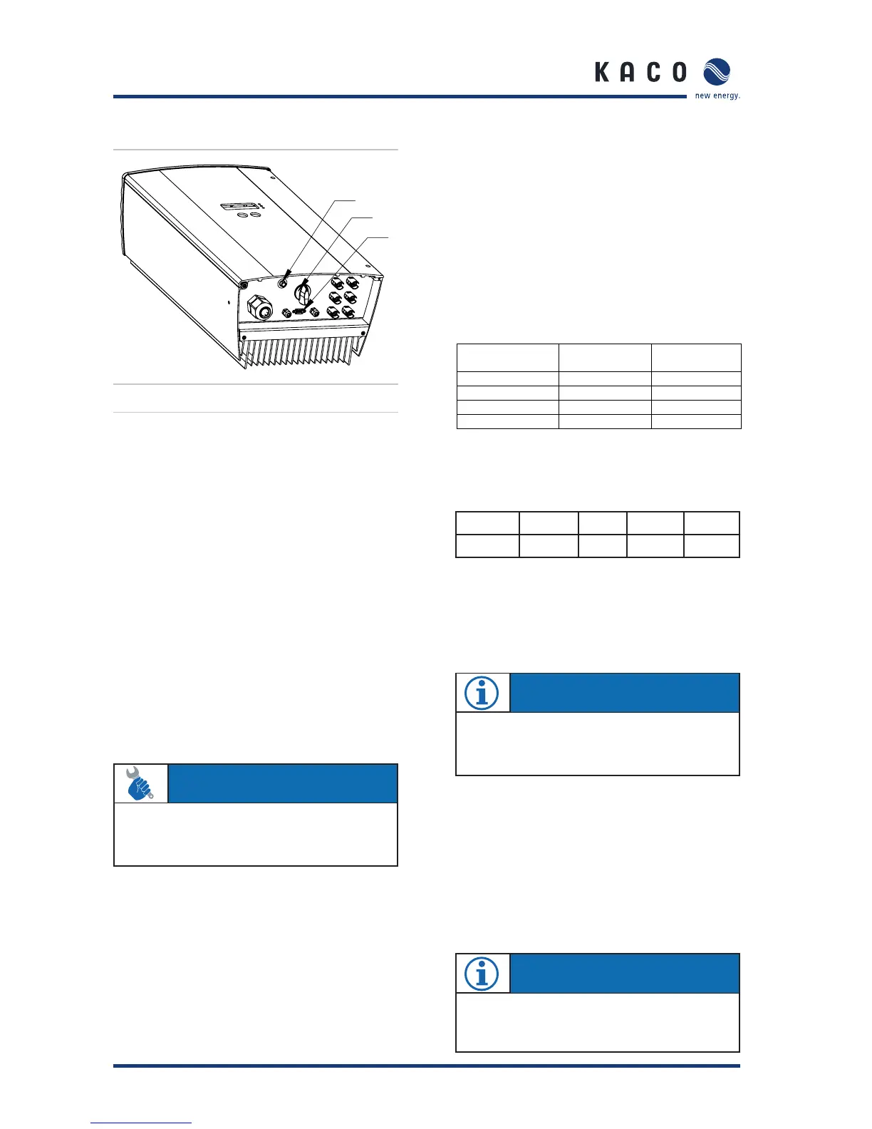
Figure 4.6: Underside of the Powador
The inverters include an internal DC disconnector, which
allows for the inverter to be disconnected from the photo-
voltaic generator in case of repair or fault.
To disconnect the inverter from the photovoltaic generator,
turn the internal DC disconnector on the underside of the
inverter from the ON (1) position to the OFF (0) position (see
fi gure 4.6).
When delivered, the inverter’s internal DC disconnector is in
the OFF (0) position.
4.7 Night start-up key
The unit switches off in the evening as nightfall approaches.
The display is no longer shown. In order to retrieve the values
from the current day, (daily yield, daily hours of operation and
max. grid feed power) after the display switches off, the unit
can also be activated during the night by pressing the night
start-up key on the underside of the inverter.
You can now scroll through the menu and retrieve the saved
values. If over one minute elapses without a key being pressed,
the unit switches off automatically once again.
The “Counter oper. hours ”, “Total operating hours”, “Coun-
ter yield”, and “Total yield” data are permanently saved and
totaled. This data remains in memory even if the inverter is
switched off for a long time.
The daily yield, daily hours of operation and the max. daily grid
feed power are available until the following morning and are
cleared when PV generator voltage is present again.
4.8 The serial RS232 interface
Operating data can be transmitted to a computer (e.g. notebook)
over a galvanically isolated serial interface (see fi gure 4.6 - (7))
from where it can then be individually processed further using
standard spreadsheet software.
A standard serial 1:1 interface cable is all that is required for
connecting the inverter to the computer. The cable length
should not exceed 20 metres.
The data from the inverter is sent unidirectionally as pure
ASCII text over the serial interface. The data is not checked
for errors.
Table 4.1: RS232 interface pin assignment
The RS232 interface has the following parameters:
Baud rate Data bits Parity Stop bits Protocol
9600 baud 8 none 1 none
Figure 4.7 shows, as an example, a few of lines of transmis-
sion via the RS232 interface.
Data can be received with any terminal emulator, which comes
with every operating system, or with the KACO-viso visualisa-
tion tool.
Together with the Powador inverter, KACO-viso takes over the
role of a data logger. It saves the data from the inverter and
displays it in various diagram types as a daily or monthly rep-
resentation.
The PC, however, must also run continuously. Because of the
amount of energy used, this type of monitoring only makes
sense over limited periods, such as during a fault analysis. For
permanent monitoring, we recommend the optional accesso-
ries (see section 5).
Section 4 · Operation
6
5
7
Powador Sub-D
male 9-polig
Bedeutung PC Sub-D
female 9-polig
2TXD 2
3RXD3
4RTS 4
5GND5
Signifi cation
male 9-pole female 9-pole
ACTION
To do this, press the “night start-up” key (see fi gure 4.6
- (6)) on the underside of the unit for approx. 5 seconds
until a display appears.
NOTE
The KACO-viso visualisation software can be down-
loaded from
http://www.kaco-newenergy.de
NOTE
With the optional accessories (see section 5), you can
also implement wireless data transmission over long dis-
tances between the inverter and your PC.
 Loading...