123 910
+
PE
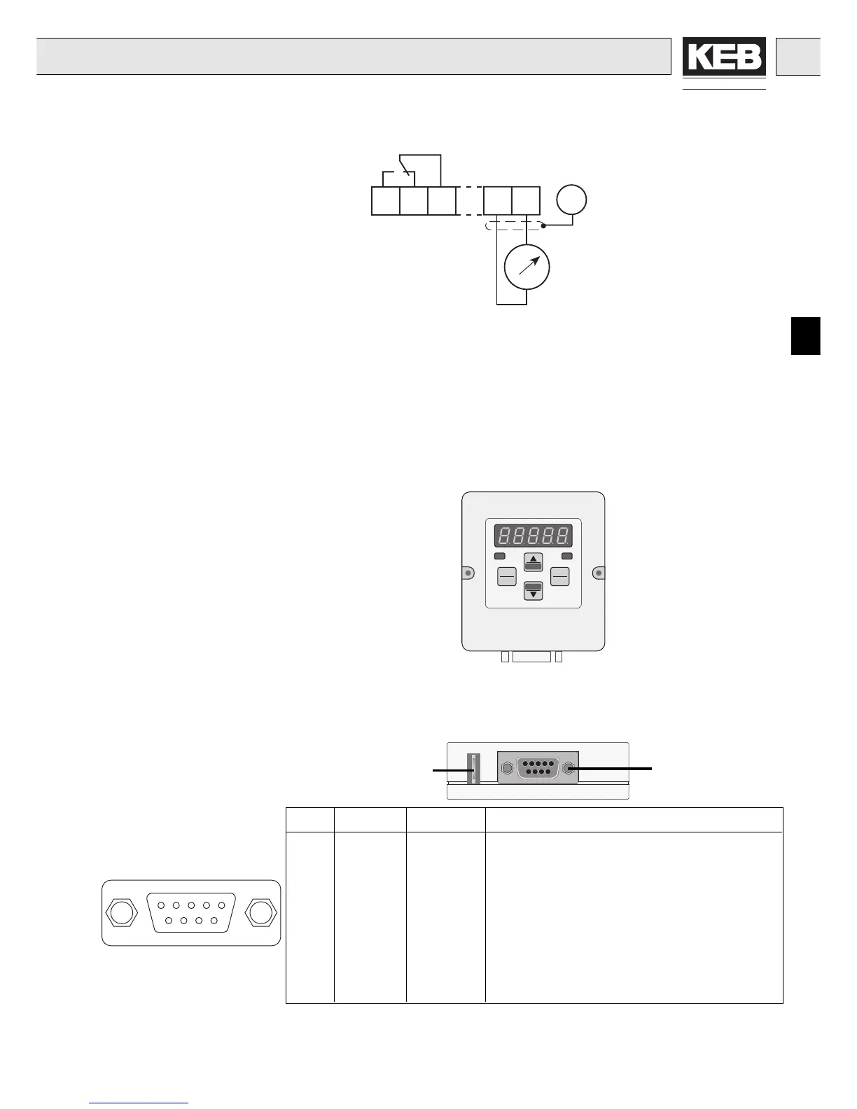
Analog output:
0...10VDC / max. 5mA
at Ri 56 kΩ const.
0...1mADC at
Ri ≤ 5 kΩ const.
3.2.3Outputs
Installation and Connection
As an accessory to the local operation an operator is necessary. To
prevent malfunctions, the inverter must be brought into
nOP
status
before connecting/disconnecting the operator (open control release
terminal X1.14). When starting the inverter without an operator, it is
started with the last stored values or factory setting. The operator is
obtainable in different versions:
4. Operation of the
unit
Interface control
Transmit "LED flickers"
Double function keyboard
Operating-/Error display
Normal "LED on"
Error "LED blinks"
5-digit LED Display
4.1 Digital operator
Part-No. 00.F4.010-2009
RS232/RS485
PIN RS485 Signal Meaning
1 –– reserved
2 – TxD Transmitter signal/RS232
3 – RxD Receiver signal/RS232
4 A' RxD-A Receiver signal A/RS485
5 B' RxD-B Receiver signal B/RS485
6 – VP Voltage supply-Plus +5V (I
max
= 10 mA))
7 C/C' DGND Data reference potential
8 A TxD-A Transmitter signal A/RS485
9 B TxD-B Transmitter signal B/RS485
PE-Connection
4.1.1 Interface operator
Part-No. 00.F4.010-1009
In the Interface operator there is an additional isolated RS232/RS485-
Interface integrated.
Informations about other versions of operators contact KEB!
Relay output:
30V DC / 1A
12345
6789
 Loading...

