5
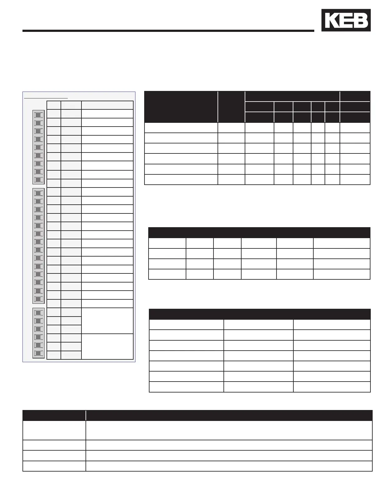
3. Control Circuit and Input/Output Logic Tables
X2A Reference
Pin Name Description
1 AN1+ Analog Input 1, +
2 AN1- Analog Input 1, -
3 AN2+ Analog Input 2, +
4 AN2- Analog Input 2, +
5 ANO1 Analog Output 1
6 ANO2 Analog Output 2
7 CRF Analog Supply, +10V
8 COM Analog Common
9 COM Analog Common
10 I1 Step Speed 1
11 I2 Step Speed 2
12 I3 No Function
13 I4 No Function
14 F Forward
15 R Reverse
16 ST Enable
17 RST Reset
18 O1 At Speed (AS)
19 O2 Drive Ready (RDY)
20 24V 24V Output
21 V
IN
20 ... 30V Input
22 0V Digital Common
23 0V Digital Common
24 NO
Relay 1
RDY
25 NC
26 COM
27 NO
Relay 2
DRO
28 NC
29 COM
AnalogDigitalRelays
Digital Speed
Selection
Input
Status
CP25
X2A Inputs Active Internal
Enable Fwd Rev I1 I2 ID
1 4 8 16 32 2048
Forward High Speed 2069 1 1 0 1 0 1
Reverse High Speed 2073 1 0 1 1 0 1
Forward Low Speed 2085 1 1 0 0 1 1
Reverse Low Speed 2089 1 0 1 0 1 1
Forward Inspection 2101 1 1 0 1 1 1
Reverse Inspection 2105 1 0 1 1 1 1
X2A Output Status, CP26
Name O1 O2 Relay 1 Relay 2 OD (Internal)
Default AS RDY RDY DRO AS LT (Internal)
Pin(s) 18 19 24...26 27...29 Internal
Value 1 4 8 16 128
Displayed below are the X2A terminal strip connections, input/output logic tables, typical run values and
output conditions and functions. The table below shows the Input Status, CP25 numerical value. It is the
sum of the individual input weightings. For example, Forward High Speed = 2069 = ST (1) + F (4) + I1 (16)
+ ID (2048).
Symbol: 1 = Input is active
0 = Input is not active
Function Conditions
At Speed (AS)
Active when Actual Motor Speed, CP28 is +/- 100 rpm (ASCL, Closed Loop) or when
CP28 is equal (Open Loop, V/Hz) to Commanded Speed, CP27 above 100 rpm.
Ready (RDY) Signal turns off when a drive fault occurs.
Drive On (DRO) Enable, direction, and motor phase current check passes. Drive is outputting current.
At Speed (AS) LT Lower threshold for At Speed. Turns on when CP28 speed is 100 rpm or greater.
The table below describes the output functions and the conditions they must satisfy to become active.
The table below shows the Output Status as displayed in CP26.
Add the outputs to determine the state.
Typical Run Values
Input Status, CP25 Output Status, CP26
Forward High Speed 2069 143
Reverse High Speed 2073 143
Forward Low Speed 2085 143
Reverse Low Speed 2089 143
Forward Inspection 2101 143
Reverse Inspection 2105 143
The table below shows typical run values for the Input and Output
Status parameters, CP25 - 26.
 Loading...


