Proper connection of the supply to the DUT 5
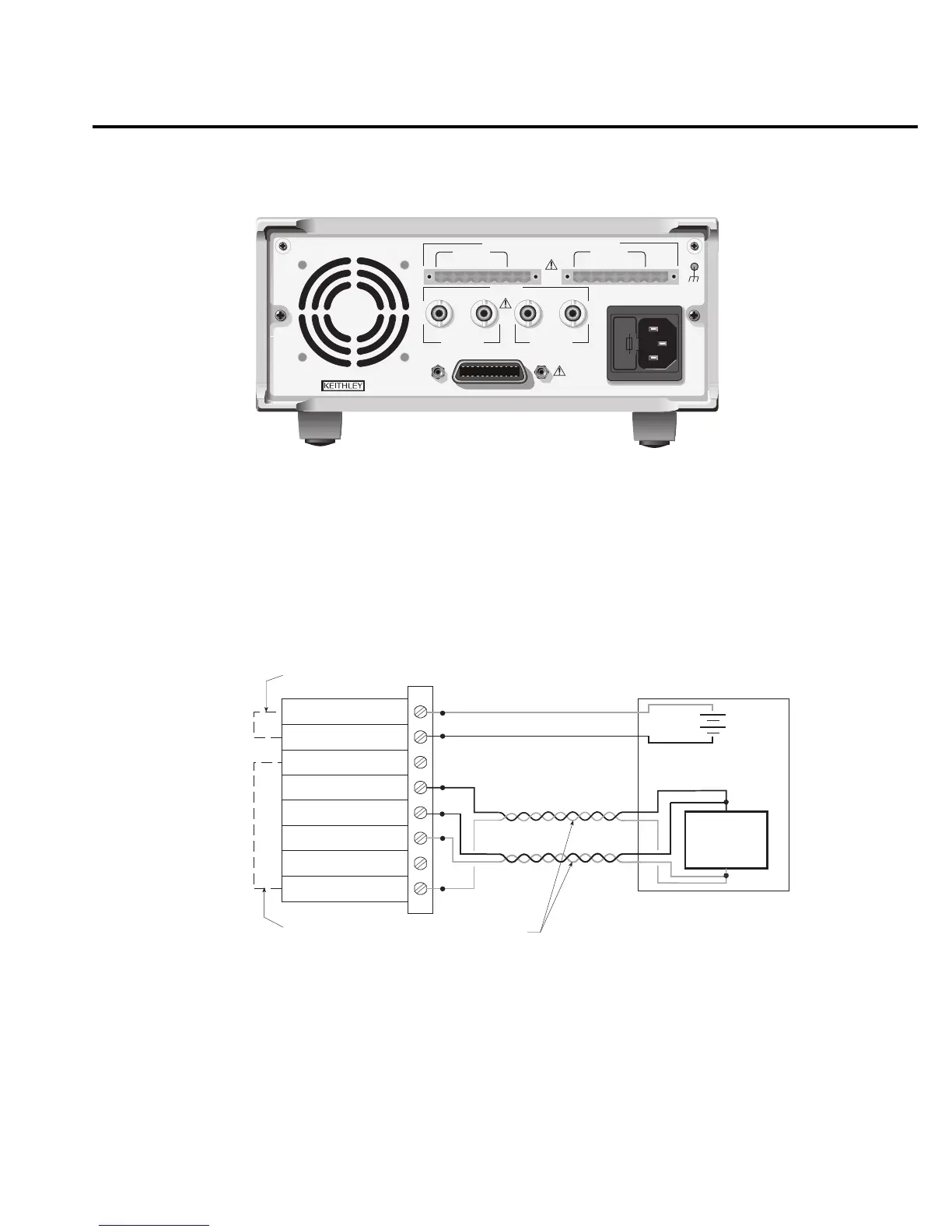
Figure 3
Rear panel view of Model 2306-VS
NOTE
The TRIGGER connectors on the rear panel of the Model 2306-VS are associated
with the external triggering and voltage stepping capabilities of the unit. See
"External triggering" on page 29 and Section 6 of the Model 2306 Instruction
Manual for details.
Figure 4
4-wire remote sense connection of the DUT to the output
NOTE
DO NOT jumper the sense inputs and supply outputs at the rear of the supply.
DO NOT pass the source and sense leads together in the same twisted pair.
WARNING:NO INTERNAL OPERATOR SERVICABLE PARTS,SERVICE BY QUALIFIED PERSONNEL ONLY.
CAUTION:FOR CONTINUED PROTECTION AGAINST FIRE HAZARD,REPLACE FUSE WITH SAME TYPE AND RATING.
MADE IN
U.S.A.
LINE RATING
100-120VAC,
200-240VAC
50, 60 HZ
150VA MAX.
LINE FUSE
SLOWBLOW
2.0A, 250V
IEEE-488
+++
____
+
DVM IN
OUTPUT #2
SOURCE SENSE SOURCE
+++
____
+
DVM IN
OUTPUT #1
SOURCE SENSE
SOURCE
ISOLATION FROM EARTH: 22 VOLTS MAX.
DVM IN
+30 VDC MAX.
TRIGGER
CAT I
IN OUT IN OUT
CHANNEL 1 CHANNEL 2
External Test Circuit
Quick Disconnect
Connector
Model 2306
source input/output
DVM input
DUT
+
-
DVM +
DVM -
Source -
Source -
Sense -
Sense +
Source +
Source +
Twisted pair
 Loading...


