Advanced features 25
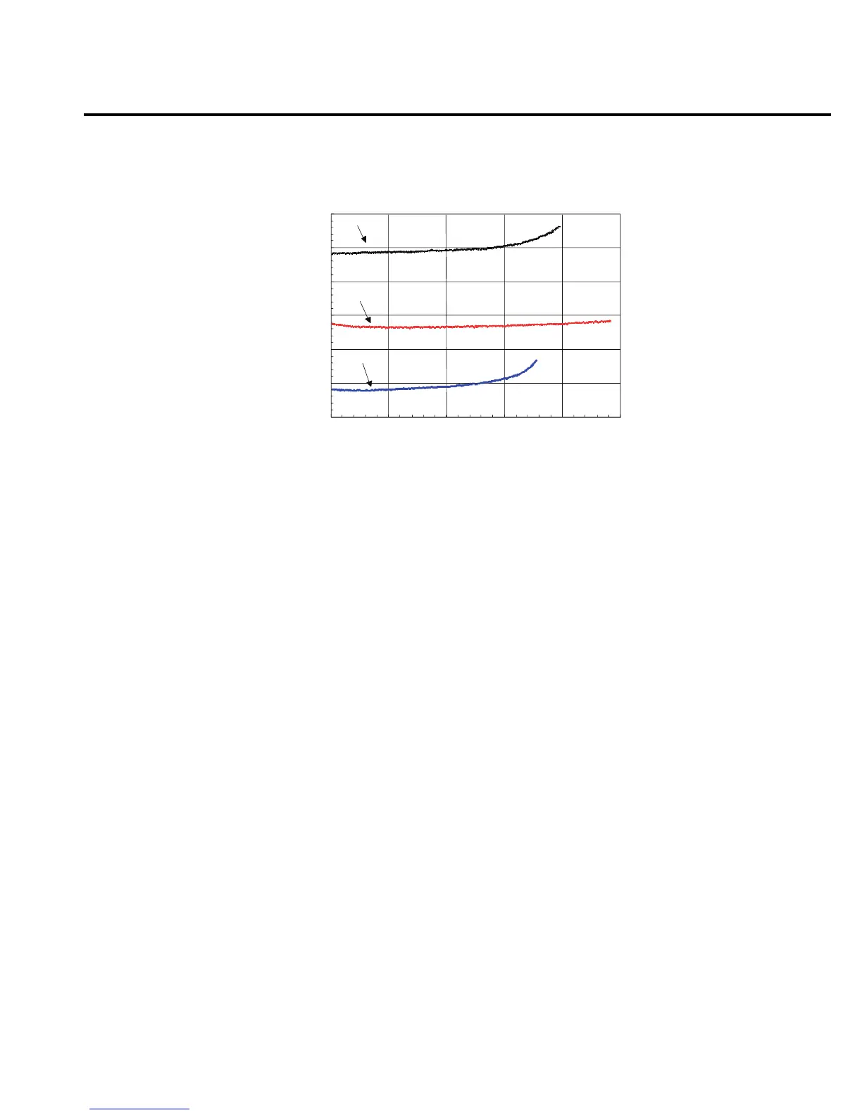
Figure 13
Electronic resistance of NiCd, NiMH, and Li ion battery packs
NOTE Figure 13 shows electronic resistance for battery packs during a simulated GSM
phone pulsed discharge from full charge to 5.5 volts.
Variable output impedance control on channel #1
Channel #1 of the Model 2306 has a variable output impedance control that can be used to
simulate the impedance of a battery pack. The output impedance may be set from 0.00 ohms
(default condition) to 1.00 ohms in 0.01 ohm increments from the front panel or over the GPIB
bus.
Figure 14 shows the output voltage and current response of channel #1 with a GSM phone
for output impedance values of 0.00, 0.05, and 0.10 ohms. The voltage drop, 70mV in c and
140mV in e, is approximately equal to the dynamic load current, 1.4A, multiplied by the output
impedance, c (0.05 ohms) and e (0.10 ohms).
Time, hrs
Output Impedance, ohms
0.0
2.0 4.0 6.0 8.0 10.0
NiMH
NiCd
Li ion
0.10
0.15
0.20
0.25
0.30
0.35
0.40
 Loading...


