3.
INSTALLATION
AND
CONNECTION
3-2.
CONNECTION
NOTE
The
following
instructions are for use by either
your KENWOOD dealer, an authorized KENWOOD
service
facility, or the factory.
WARNING
Never
connect AC power to the DC Power Supply
until
installation is complete.
3-1.
INSTALLATION
CAUTIONS
1.
Prior to installation, check that the correct fuse
is
installed.
2.
Choose a location that is relatively free
from
vibration.
3.
Do not place the
unit
in a place which is
exposed
to direct sunlight, near a heater, etc.
4.
Do not store or use the
unit
in a dusty location
or in a moist atmosphere. Select a well
ventilated location.
5.
To maintain
good
ventilation:
Remove
the packing materials.
Do not cover the
unit.
Place
the
unit
at least 10 cm (4") away
from
the walls.
6.
(With the Europe and the General Markets
version
only)
Prior
to installation, check that the AC Voltage
Selector
on the side panel is set to the correct
line voltage.
AC
VOLTAGE
SELECTION
With the Europe and General Markets version)
CAUTION
Make sure that the AC cable is disconnected
before selecting an AC voltage.
When changing an AC operating voltage, select the
desired
voltage
with
the selector switch located on
the side cover. In this
case,
the correct fuse must
be installed, referring to Section 5-4.
FUSE
REPLACEMENT.
WARNING
Never
connect AC power to the DC Power Supply
until
installation is complete.
CAUTIONS
1.
Before connecting or disconnecting the DC
Power
Cable,
be sure to
turn
off the
POWER
switches
of
both
the radio and the DC Power
Supply.
2.
Observe polarity of the DC Power
Cable.
The
radio operates on 13.8
VDC,
negative ground.
NOTES
1.
The DC Power Supply will not operate if the
output
terminals are shorted.
2.
The DC Power Supply may not operate if the
POWER
switch is turned on
with
the radio in
transmit mode because the protection circuit
may
operate.
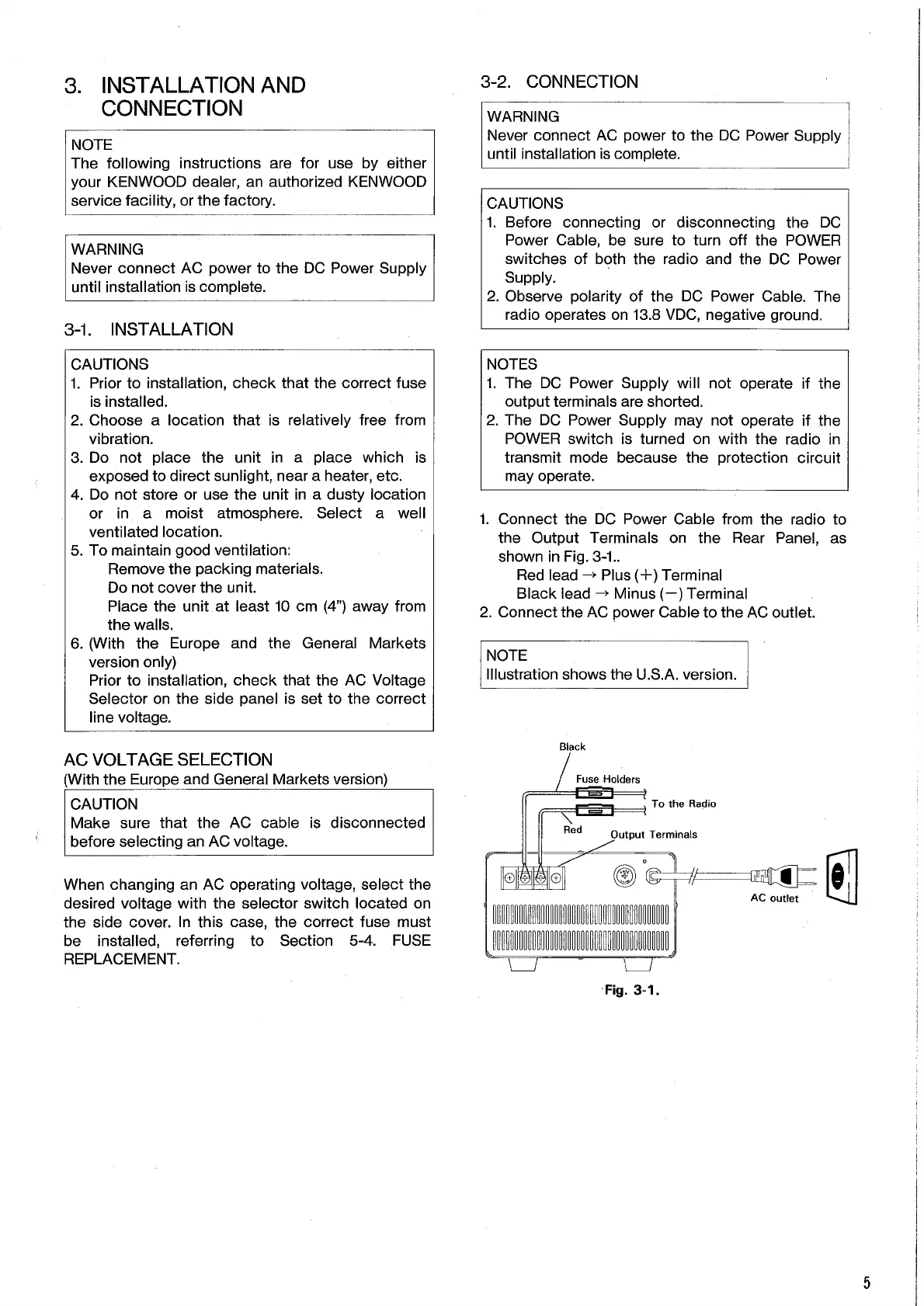
1.
Connect the DC Power Cable
from
the radio to
the Output Terminals on the
Rear
Panel,
as
shown in
Fig.
3-1..
Red
lead ->
Plus
(+) Terminal
Black
lead -> Minus
(—)
Terminal
2.
Connect the AC power Cable to the AC
outlet.
NOTE
Illustration shows the
U.S.A.
version.
Fig.
3-1.
5
Black
Fuse Holders
To the Radio
Red
Output Terminals
AC outlet
 Loading...