4. Rotate the tuning control or press the
UP
I DWN
switches
on
the microphone until the
des1red
tuning
step size appears in the display.
5.
To complete the programming of the step size you
can press any key
on
the front panel except the
POWER
key, or simply wait 10 seconds and the
microprocessor will automatically return to the
normal frequency display.
The chart below shows how the microprocessor will
correct a
new
step size.
5,10,15,20 to 12.5,25
12.5,25
to 5,10,15,20
R
.5.10.15
··~~
-.,..oa····--:
6,25,30,35 i
25
'-----:::io-C:,4:is-':::.so.ss
~-
so
I
.
6o,65,7o,75,
75
I
. 80,85,90,95 .J
0 0
~
,_
...
··-
i 12.5
10
f---·-·······
__
..
_
I 25
20
I
37.5
30
50
50
62.5
'
60
I
75
.
'
70
I
87.5
I
80
18
5-2-4 Programmable
VFO
Tuning
Umits
The TM-2411 4411541 series radios provide the capabil·
ity
of
programming the
VFO
tuning range, in 1 MHz
band segments,
as
well a providing a separate program·
mabie band scan function(See page 26). For example
you could tell the transceiver that you only wish to tune
the
144
MHz and
145
MHz band segments. The tuning
controls and microphone
UPIDWN
switches would then
only
tune within these specific frequency limits.
The
procedure for specifying these limits is described below.
1.
Press the VFOIM..,V key to select the
VFO
mode.
2.
Rotate the tuning control or press the microphone
UP
I
DWN
switches until the desired lower tuning
range appears in the frequency display.
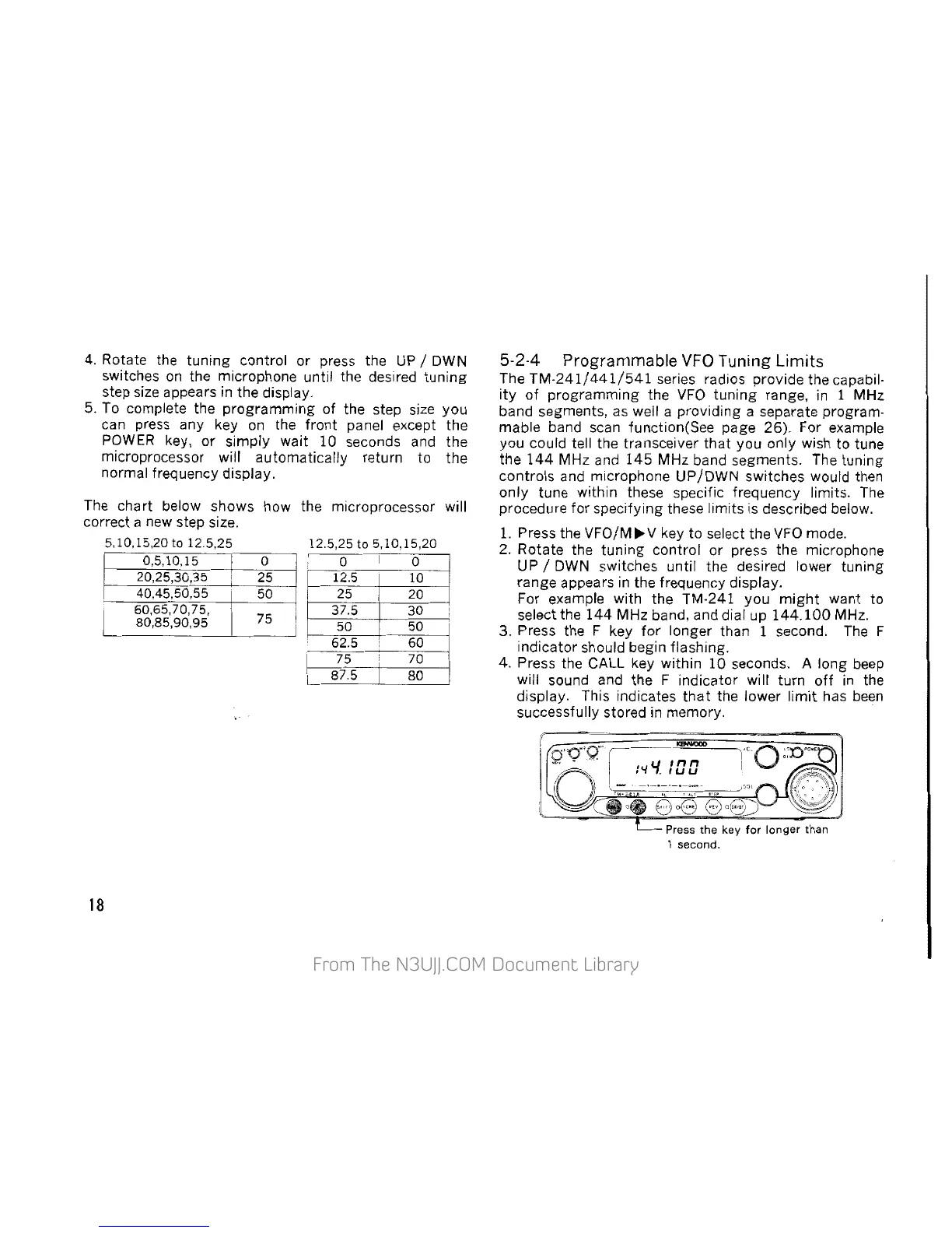
For example with the TM-241 you
might
want to
select the
144
MHz band. and dial up
144.100
MHz.
3. Press the F key
for
longer than 1 second.
The
F
indicator should begin flashmg.
4. Press the CALL key within 10 seconds. A long
beep
will sound and the F indicator will turn
off
in the
display. This indicates
that
the lower
limit
has
been
successfully stored in memory.
Press
the
key
for
longer
than
1
second.
 Loading...