EN
16
No equalized charging mode for GEL batteries.
For barriers ALT3/4/6 do not connect LED lights on boom
and disconnect double colour led discs on the barrier (only
possible to connect RED led with ashlight function).
See instruction of barrier control unit.
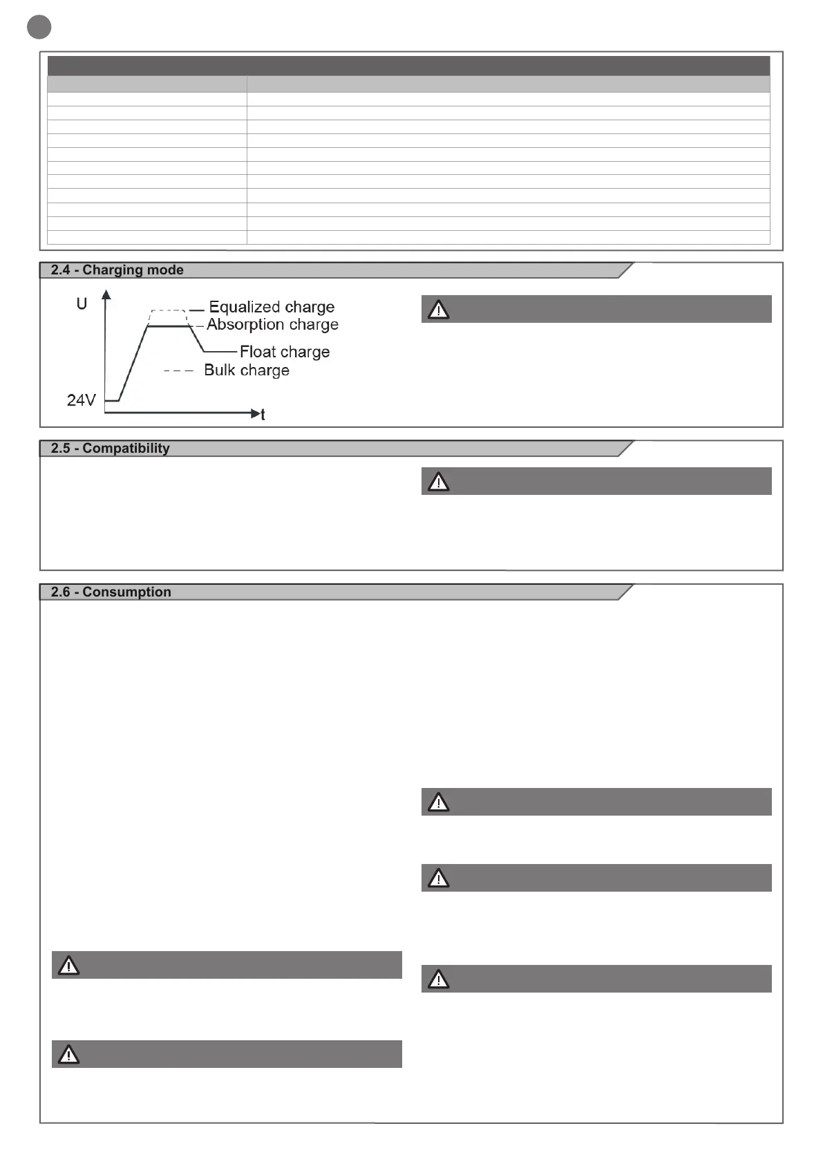
2.4 - Charging mode
2.5 - Compatibility
2.6 - Consumption
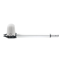
The Key Solar Kit is compatible with the following 24V motors:
Sliding Gate Motors: SUN series 24V, TURBO series 24V
Swing Gate Motors: RAY series 24V, Star 200 24V, Star 500
24V, REVO, MEWA 24V, UNDER 24V
Barriers: ALT series
It is possible to estimate the power consumption and thus the
number of maneuvers possible by the SOLE KIT, correlating
the total system power consumption and the power supplied by
the batteries.
Below (see table pag. 6) are the standby power consumption of
devices that are commonly powered by the system.
To calculate the daily consumption of the system, follow the
installation example (Par. 2.7).
Dayly consumption is the sum of 4 factors:
1. A= consumption in stand-by mode when the gate is closed;
2. B= consumption when the gate is open and not in move-
ment;
3. W= consumption when the gate is moving opening + closing;
4. NLS= activation of the Night Light System during night hours
(optional)
Dayly consumption= A+B+W+NLS
For the correct use of the kit, make sure that daily consumption
does not exceed the power supplied by solar panel.
Key Automation strongly suggest to use GEL batteries 12V,
18Ah, AGM (absorbent glass mat) type.
Accessories will draw additional power from the battery;
the more accessories you connect, the more power your
system will require.
The SOLE KIT solar powered system is intended for resi-
dential applications and light commercial gate operation
with limited cycles per day.
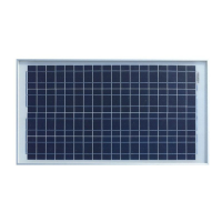
SOLAR PANEL
PARAMETERS VALUE
Model SLP030W - 24V
Cells polycrystalline silicon solar cell
Irradiance and Cell Temperature 1000W/m² AM1.5 25°C
Peak Power (Pmax) 30W
Voltage at Pmax (Vmp) 34.4V
Current at Pmax (Imp) 0.87A
Open circuit Voltage (Voc) 43.2V
Short-circuit Current (Isc) 0.96A
Operating temperature -40+85°C
Dimensions 510 x 541 x 30 mm
Weight 3,75 k g
While our system can operate over 30 cycles and/or provide
over 1 week of standby time on fully charged batteries, it needs
enough standby time to fully recharge the batteries or it will
eventually run out of charge to operate the system.
We highly recommend to keep the system as simple as pos-
sible and avoid adding accessories that draw current from the
batteries. The KEY AUTOMATION control units manages ener-
gy consumption and powers down all components, accessories
and peripherals that are not required to operate when the gate
is fully closed.
YOU MUST ACTIVATE THE STAND-BY FUNCTION. STAND-
BY FUNCTION IS ACTIVATED WHEN THE GATE/BARRIER
IS TOTALLY CLOSED.
For barriers ALT3/4/6 do not connect LED lights on boom
and disconnect double colour led discs on the barrier (only
possible to connect RED led with ashlight function). See
instruction of barrier control unit.
NEVER USE THE SOLAR PANEL AND THE AC TRANSFORMER
AT THE SAME TIME (FIG. 6)
For a balanced system your Solar Panel should recieve at least
6 hours of direct sunlight.
To calculate solar radiance in your area consult the web.
ATTENTION !
ATTENTION !
ATTENTION !
ATTENTION !
ATTENTION !
ATTENTION !
ATTENTION !
 Loading...