EN
20
4 - INSTALLING THE PRODUCT
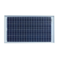
4.2 - Solar panel
Even a slight shade (e.g. a leaf) on the panel will drastically
reduce the performance of the system. It is mandatory that the
panel is always completely exposed to sunrays.
ATTENTION !
To correctly position the solar panel, the following is required:
- Check that the desired installation position is always sunny (direct
sun rays), all daylong and all days of the year.
- Check that the position is far from trees, bushes, buildings or any
other object which might project shade on the panel surface.
Once the most convenient installation position has been selected,
the solar panel should be correctly oriented:
For countries north of the Equator, the panel must be oriented to
wards the SOUTH.
For countries south of the Equator, the panel must be oriented to
wards the NORTH.
The panel can be installed using Solar Panel Mount bracket (par.3)
on xed, at or pole mount.
Firmly x the panel to avoid loosening causing incorrect tilt angle.
According to the installation latitude, the panel should be tilted with
respect to the ground, with an angle α (fig.4) which must be calcu-
The mounting kit is a xed, at or pole mount design giving a tilt
angle range of 0° - 90°.
To x the mount bracket you have to assemble the components
and parts together (g 2). We suggest you lubricate all nuts and
bolts to facilitate easy removal at a later date. Attach the tilt arm
and xed bracket to the middle part of the PV module frame using
M8 module bolts and M8 mounting bolts along with washers, lock
washers and nuts.
To adjust the tilt angle of the PV panel, change the location of M8
bolts in the arc hole of the tilt arms. Remember to use lock wa-
shers to prevent vibration from working them loose.
For pole mounting, use hose clamps (not included) to x the PV
module and mount assembly securely to the pole (g 3.1).
The dyna bolts are not included in the kit.
Note: For vertical wall mounting, drill holes on the mounting place
to be installed according to size of the xed bracket. Embed two
M8 dyna bolts into the mounting surface (g 3.2). Use washers
lock washers and nuts to secure the PV module and mount assem-
bly to the wall surface.
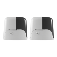
4.1 - Solar panel mount bracket
Additional mounting holes may be required if using this mount
with a panel other than the PF30W. Great care should be taken
when drilling additional holes as damage to
the panel can easily occur, rending it useless.
ATTENTION !
lated based on the following table:
Latitude Tilt angle α *
0-15° 15°
15-25° same value as the latitude
25-30° Add 5° to the latitude value
30-35° Add 10° to the latitude value
35-40° Add 15° to the latitude value
> 40° Add 20° to the latitude value
* Tilt angle is an average for all seasons. For specic tilt angles for
each season in your area consult the web
As it can be noted, the farther from the equator, the more the panel
should be tilted towards the horizon to oset the sunrise-sunset path
and therefore obtaining as much sun irradiation as possible. With
the increasing of the latitude values, in fact, the sun path is lower
with respect to the horizon.
A correct orientation is of key importance for the highest perfor-
mance of the PV panel.
If the latitude angle of the installation area is unknown, some latitude
values of various towns worldwide are included in this instruction
manual (g. 7), for reference purposes.
See gure 5 for the circuit layout. Wiring of batteries and ground
are pre-wired. Connect cable 1 and 2 as in gure 5 and see par.
4.4 for the technical specication.
Make sure battery and solar panel are disconnected to controller,
and do not connect the positive and negative terminals of solar
panel and battery at the same time to avoid of electric shock.
Make sure installation site meets safety requirements rst.
Make sure voltage of solar panel and battery are compatible with
controller.
Connect battery to controller and check whether the LCD display
is on, if not, please solve the problem as mentioned in chapter 6
(pag.9).
Connect solar panel to controller accordingly. If there’s sunlight,
controller starts charging battery immediately and charging indica-
tor arrow on LCD on. Connect load to controller.
4.3 - Solar charge controller
4.4 - Cable and cable glands
Key Automation strongly suggest to use the following specication for the cable 1 and 2 (g.5)
CABLE 1 CABLE 2
Type H05RNF/H07RNF H07RNF
Diameter > 2×1,5 mm² > 2×4 mm²
Lenght < 20 m < 5 m
Cable glands PG16 PG21
4.5 - Wiring
NEVER USE THE SOLAR PANEL AND THE AC TRANSFORMER
AT THE SAME TIME (FIG. 6)
ATTENTION !
 Loading...