2.12.2 Communication Setup Submenu
Modbus
®
Communications
The controller communicates using Modbus
®
as a slave connection with the Modbus
®
master initiating the communication. The
controller seeks the system and alternator parameters and diagnostic information then responds back to the Modbus
®
master.
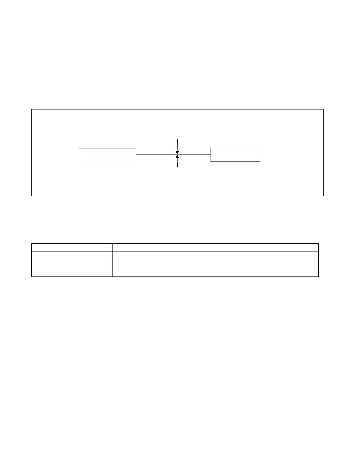
In addition, the controller accepts information to alter controller parameters including generator set starting and stopping. See
Figure 12. Refer to the List of Related Materials for available Modbus
®
literature.
Note:
Only one Modbus
®
master can be connected to the controller. Examples include the remote serial annunciator, monitoring
software, and switchgear applications.
Figure 12 Modbus
®
Connections
A controller can communicate directly to a Modbus
®
master or participate in a network of devices. It can also be used to interface
a local master to a network of devices.
The Modbus
®
master polls slave devices for data. Controller devices are slaves. Examples of master devices are a personal
computer running monitoring software and the remote serial annunciator
9600, 19200, 38400, or 57600.
Must match the master PC and all devices in the system.
Figure 13 Decision-Modbus
®
3500 Communication Parameters
Select the baud rate. Choose the same baud rate for the Modbus
®
master, modems, and connected devices. See Figure 13.
Each generator set controller must have a unique Modbus
®
address and PGEN node number (1-4).
Note:
The PGEN node number is automatically determined. The number of nodes online should match the number of installed
generators.
Note:
The PGEN baud rate should not be adjusted except under direction from a factory service representative. Different baud rates
between controllers on the network will result in a loss of communication on the network.
Modbus
®
is a registered trademark of Schneider Electric.
 Loading...


