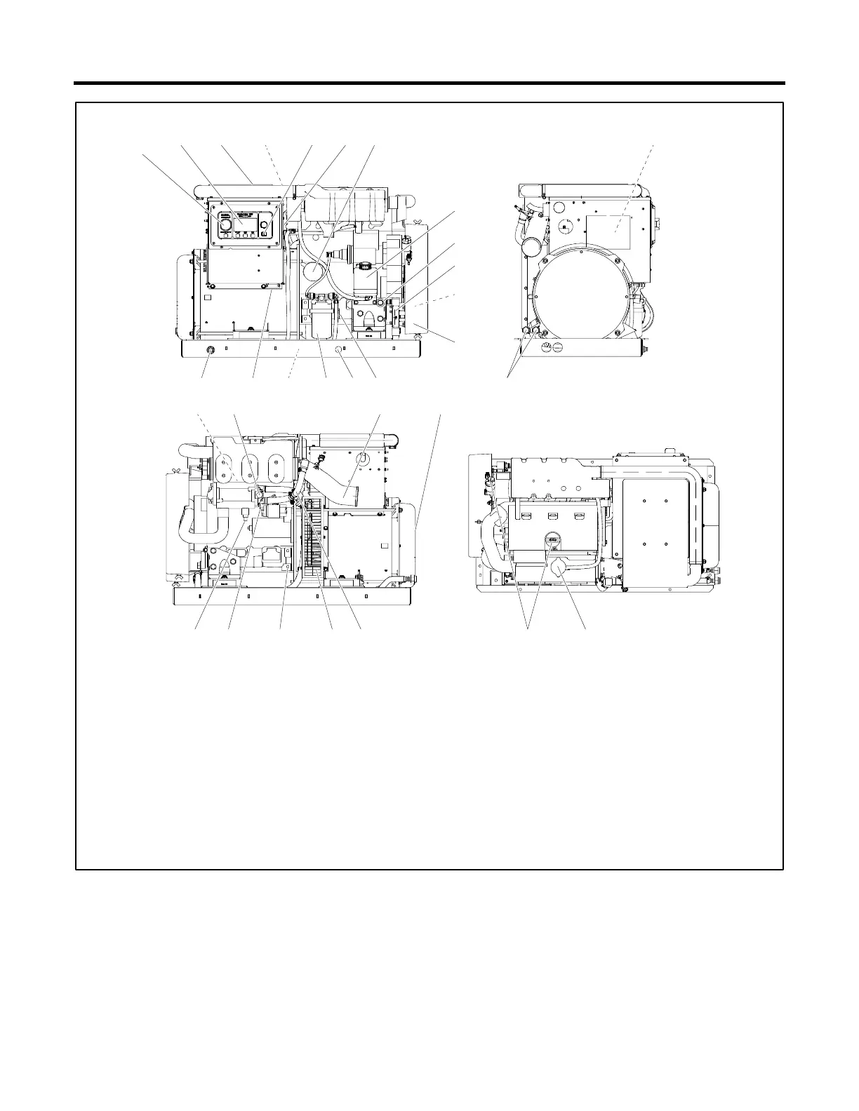
17. Customer load lead connection
2. Decision-Maker
®
3500 controller
3. Nameplate (on front of controller)
19. Optional circuit breaker location (opposite side of junction box)
20. Fuel supply and return (fuel lines are coiled and tied to unit when shipped)
21. Heat exchanger internal to exhaust manifold
6. EGR lamp (on side of junction box)
(21/24EKOZD (60 Hz) models only)
22. Anticorrosion zinc anode
23. Mixing elbow (water outlet/exhaust outlet)
8. Coolant overflow bottle
24. Alternator cooling air inlet
26. Battery positive (+) connection
11. V-belt (Seawater pump)
27. Battery negative (-) connection
29. Seawater drain (remove hose clamp)
15. Fuel filter
16. Fuel pump
31. Coolant fill/coolant overflow tube
Figure 3 Service Views—Typical (14-24EKOZD and 12-20.5EFKOZD Models)
Note:
Consult installation drawings in the spec sheet or installation manual for more details. Consult an authorized distributor/dealer
or the service manual for items not shown.
 Loading...


