TP-6811 7/1678 Section 6 Component Testing and Adjustment
Hazardous voltage.
Can cause severe injury or death.
Operate the generator set only when
all guards and electrical enclosures
areinplace.
Moving parts.
WARNING
Disconnecting the electrical load. Hazardous voltage can
cause severe injury or death. Disconnect the generator set
from the load by turning off the line circuit breaker or by
disconnecting the generator set output leads from the transfer
switch and heavily taping the ends of the leads. High voltage
transferred to the load during testing may cause personal
injury and equipment damage.
Testing the photo transistor circuit board. Hazardous
voltage can cause severe injury or death. When the end
cover is removed, do not expose the photo transistor circuit
board mounted on the generator set end bracket to any
external light source, as exposure to light causes high voltage.
Keep foreign sources of light away from the photo transistor
circuit board during testing. Place black electrical tape over
the LED on the circuit board before starting the generator set.
Note: A flashlight is required for this test of the LED
optic board.
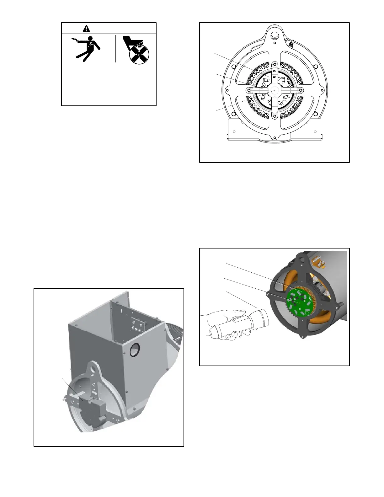
1. Remove the junction box panels from the
generator end of unit and remove the
phototransistor board cover (38RCL) or the LED
optic board and holder (48RCL, 48RCLA, and
60RCL). See Figure 6-3 or Figure 6-4.
GM84998
1. Phototransistor board/LED board cover
1
Figure 6-3 Phototransistor Board Cover (38RCL)
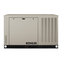
TP-6783-3
1. FRX activator board
2. LED optic board holder
3. LED optic board
1
2
3
Figure 6-4 FRX Activator Board with LED Optic
Board Installed (48RCL, 48RCLA, and
60RCL)
2. Refer to the respective generator set controller
operation manual for starting/stopping procedures.
With the generator set running at no load, shine a
flashlight at the exposed photo transistor on the
photo transistor board or FRX activator board. See
Figure 6-5.
1
2
3
1. FRX activator board
2. Photo transistor
3. Flashlight
TP-6783-3
Figure 6-5 LED Flashlight Test (48RCL shown)
3. Observe the AC output voltage controller display or
connect a voltmeter to the output leads. High AC
output voltage indicates the SCR assembly and
phototransistor board (38RCL) or the FRX
activator board (48RCL, 48RCLA, and 60RCL) are
functioning properly. The fault is likely in the wiring,
controller with voltage regulator, or LED optic
board as the output voltage should drop to low level
when the flashlight is removed. If no output is
observed, check the SCR assembly and
 Loading...


