TP-6811 7/16 79Section 6 Component Testing and Adjustment
phototransistor board (38RCL) or the FRX
activator board (48RCL, 48RCLA, and 60RCL).
See the alternator service manual for further
instructions.
4. If high output voltage exists with the flashlight off,
stop the generator set and place a small piece of
black electrical tape over the photo transistor.
Restart the unit.
If the output voltage is reduced, there is a source of
external light contamination. STOP the generator
set. Find the external light source and eliminate it
or block it from reaching the photo transistor.
If the output voltage remains high, there is a failure
in the SCR assembly and phototransistor board
(38RCL) or the FRX activator board (48RCL,
48RCLA, and 60RCL).
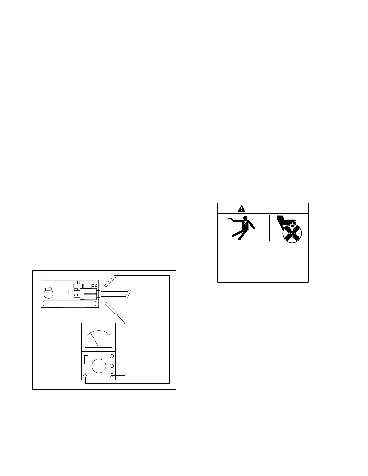
5. With the generator set running at no load,
approximately 1--2 volts DC should be observed at
3B (+) and 5B (--) at the LED optic board. See
Figure 6-6.
6. Shine the flashlight on the photo transistor. The DC
voltage reading should drop, showing that the
controller with voltage regulator is functioning.
If voltages are not observed, check the F3 fuse in
the controller and refer to the the following sections
for further information regarding the voltage
regulator adjustment and troubleshooting.
7. STOP the generator set.
TP-6783-3
V
KEEP P6
CONNECTED
(+)
(--)
Figure 6-6 Checking LED Optic Board Voltage
6.3 Voltage Connections
Generator sets equipped with a 12-lead alternator are
reconnectable to the following configurations: Delta,
Low Wye, High Wye, Dogleg. See the generator set
Installation Manual, TP-6809, for reconnection
instructions and diagrams. Generator sets equipped
with a 4-lead alternator are not reconnectable.
Setting the system voltage above 300 VAC will cause
the controller to automatically switch from a low wye to a
high wye configuration. Use Kohlerr SiteTecht
Software or the controller keypad to update the System
Voltage and Phase Connection when the alternator
voltage connections are changed.
6.4 Additional Alternator Service
Information
Refer to the alternator service manual for additional
alternator testing and service information.
6.5 Voltage Adjustments
Hazardous voltage.
Can cause severe injury or death.
Operate the generator set only when
all guards and electrical enclosures
areinplace.
Moving parts.
WARNING
Testing live electrical circuits. Hazardous voltage or
current can cause severe injury or death. Have trained and
qualified personnel take diagnostic measurements of live
circuits. Use adequately rated test equipment with electrically
insulated probes and follow the instructions of the test
equipment manufacturer when performing voltage tests.
Observe the following precautions when performing voltage
tests: (1) Remove all jewelry. (2) Stand on a dry, approved
electrically insulated mat. (3) Do not touch the enclosure or
components inside the enclosure. (4) Be prepared for the
system to operate automatically.
(600 volts and under)
Short circuits. Hazardous voltage/current can cause
severe injury or death. Short circuits can cause bodily injury
and/or equipment damage. Do not contact electrical
connections with tools or jewelry while making adjustments or
repairs. Remove all jewelry before servicing the equipment.
Note: For voltage calibration instructions, see
Section 3.7.
 Loading...