TP-6773 5/12a 33Section 6 Electrical System
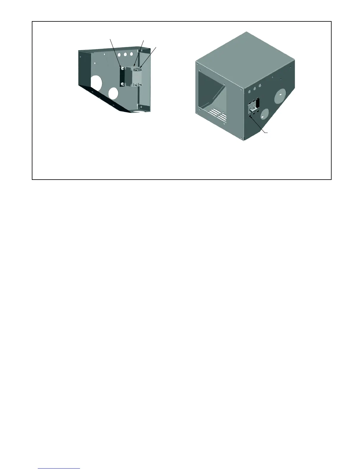
GM77889-B
1. Coverplate (qty. 2 for 1-pole kits or qty . 1 for 2-pole kits).
Use existing hardware
2. Circuit breaker
3. Jumper terminal (if supplied in kit)
4. Use existing hardware
1
3
2
4
Junction Box
(Inner View)
Junction Box
(Outer View)
Figure 6-4 Circuit Breaker Mounting
6.3 Installation In Steel or
Aluminum Vessels
Installation of a generator set in a vessel constructed of
a material capable of conducting current (e.g., steel or
aluminum) is subject to considerations not normally
encountered in fiberglass or wood vessels. These
differences include equipment grounding, grounding of
neutral conductors, ground-fault protection, and
isolation of galvanic currents.
Note: Isolated ground kits are available as options for
steel- or aluminum-hulled vessels. Consult your
local dealer/distributor for more information.
The scope of these topics is too extensive to be fully
discussed here. Consult your local marine authority for
more information.
Before installing the generator set, check the available
wiring diagrams in the operation manual to become
familiar with the electrical system.
6.4 Installation Regulations
The U.S. Coast Guard governs generator set
installation in U.S. pleasurecraft and commercial
vessels. Refer to the applicable regulations below:
U.S. Pleasurecraft Installation
Regulations
Title 33CFR, Chapter I, U.S. Coast Guard, Part 183
1. Subpart I—Electrical Equipment
2. Subpart J—Fuel Systems
U.S. Commercial Vessel Installation
Regulations
Title 46CFR, Chapter I, U.S. Coast Guard
1. Part 111—Electrical Systems
2. Part 182—Machinery Installation
m:sc:001:001

 Loading...


