TP-6773 5/12a 37Section 7 Installation Drawings
Section 7 Installation Drawings
Use the drawings in this section for installation
purposes. Consult the supplier and verify that the
drawings are the most current for your specifications.
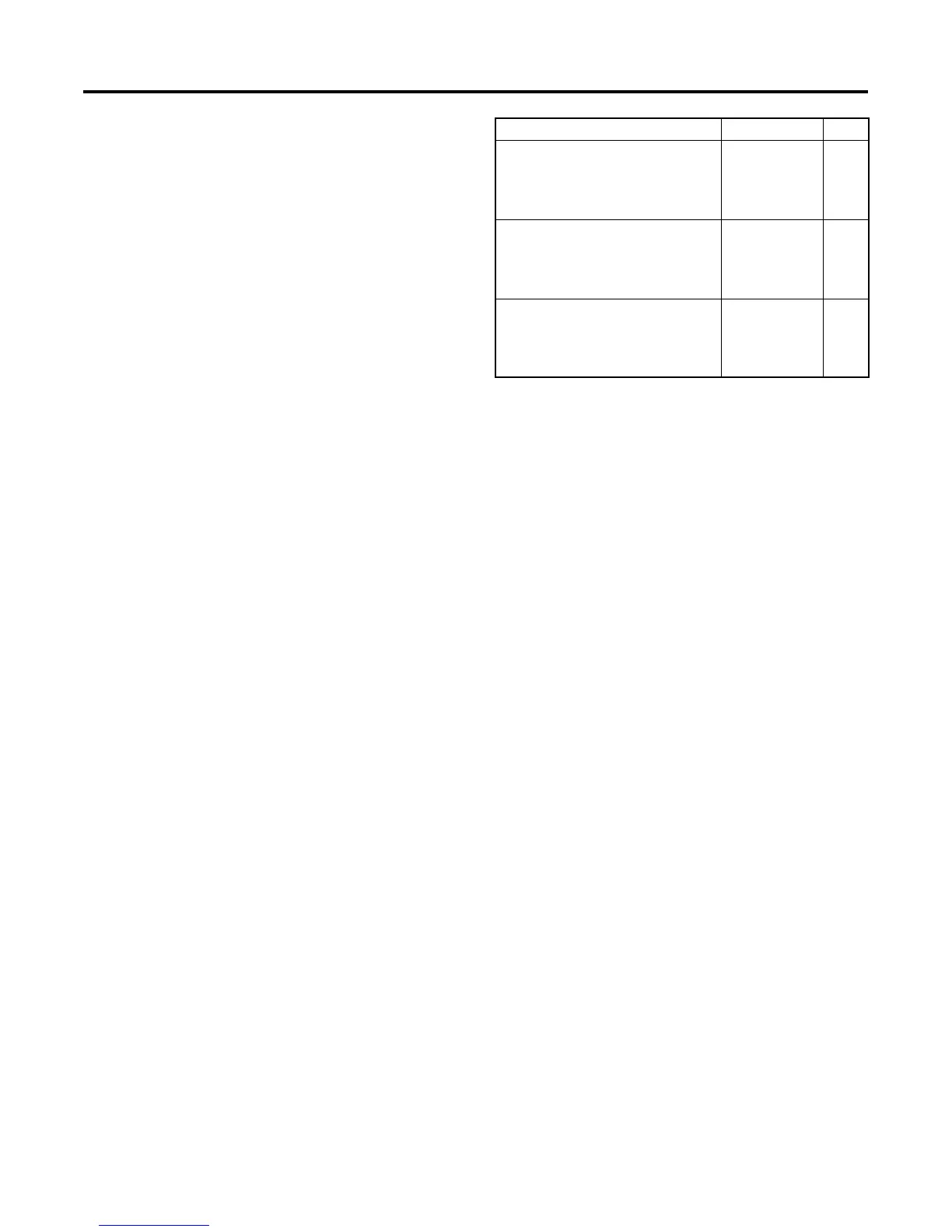
Installation drawings show exhaust outlet locations, fuel
inlet and return connections, siphon break locations,
and battery connections. See Figure 7-1 for installation
drawing identification.
Model No. Drawing Page
6EKOD and 5EFKOD
(1 phase)
ADV-7941A-A
ADV-7941B-A
38
39
with sound shield ADV-7943-A 42
with keel cooling ADV-7944-A 43
9EKOZD and 7EFKOZD
(1 phase)
ADV-7942A-A
ADV-7942B-A
40
41
with sound shield ADV-7943-A 42
with keel cooling ADV-7944-A 43
11EKOZD and 9EFKOZD
(1 and 3 phase)
ADV-7942A-A
ADV-7942B-A
40
41
with sound shield ADV-7943-A 42
with keel cooling ADV-7944-A 43
Figure 7-1 Installation Drawings

 Loading...


