TP-6773 5/12a 35Section 6 Electrical System
6.7 Remote Connection
Kohler Co. offers several remote panels for connection
to the generator set. Contact your local Kohlerr
distributor/dealer for detailed descriptions. See
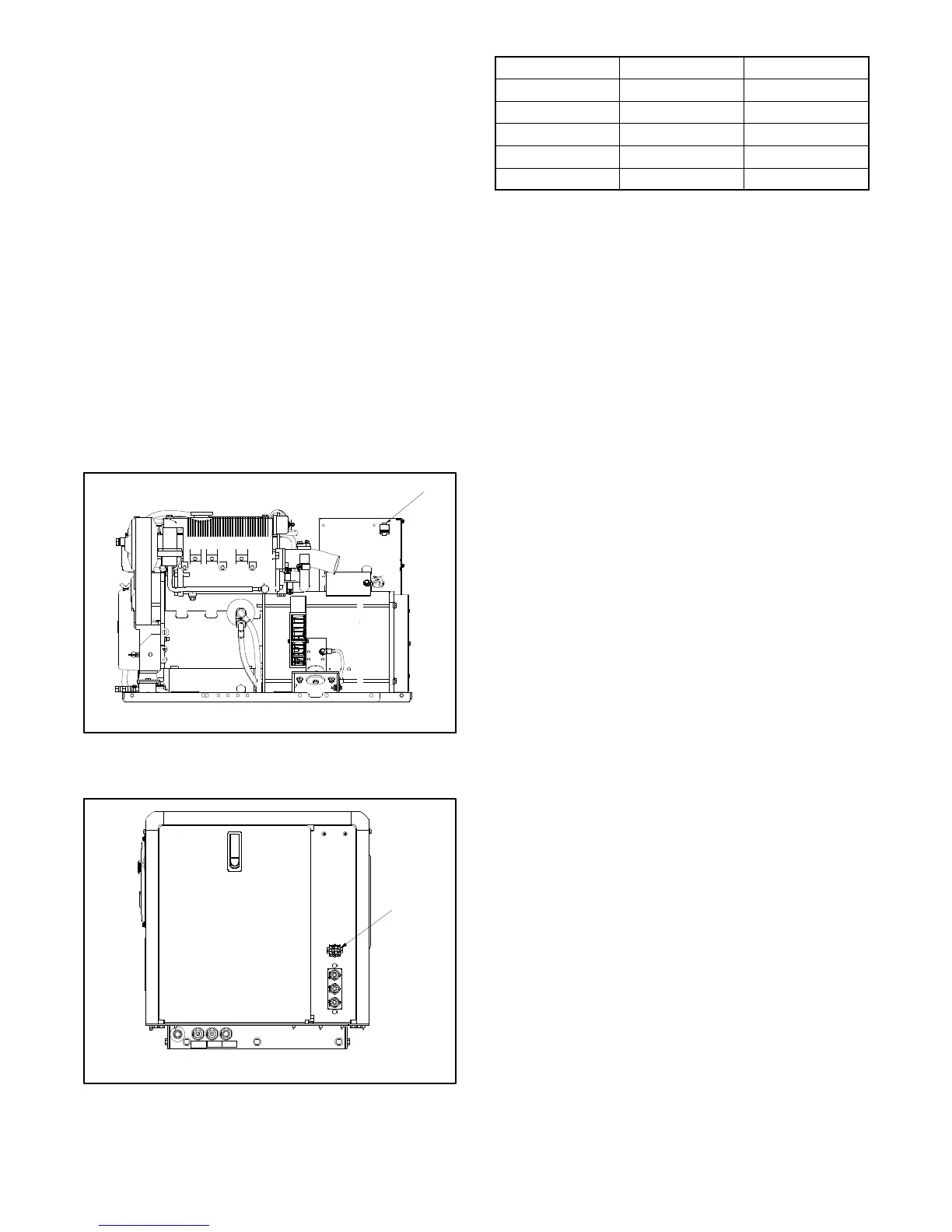
Figure 6-7 or Figure 6-8 for the location of the remote
start panel connection to the generator set controller.
Kohler Co. also offers wiring harnesses in various
lengths with a connector keyed to the controller box
connector. A “pigtail” harness is also offered which
includes the appropriate connector on one end and has
pigtails that the installer can use to connect to a
customer-supplied start/stop switch or separate lights
and hourmeter. Consult wiring diagrams, ADVs, and
instruction sheets for connection information/details.
These models use a 12-pin connector for the remote
interface connection. For the connector’s location, see
Figure 6-7 (non sound shielded unit) or Figure 6-8
(sound shielded unit). See Figure 6-9 for the correct
customer-supplied plug and pin part numbers.
1
ADV7942-A
1. Remote interface connector
Non Service-Side View
Figure 6-7 Remote Customer Interface Connector,
(Shown on a Non-Sound Shielded Unit)
1
ADV7943-A
1. Remote interface connector
Figure 6-8 Remote Customer Interface Connector,
(Shown on a Sound Shielded Unit)
Component Amp Part No. Kohler Part No.
Plug 350735-1 229998
Pin 350218-6 241618
Cable Seal 794280-1 GM29252
Interface Seal 794279-1 GM29507
Cavity Plug 770377-1 GM28769
Figure 6-9 Connector Components
Note: Gauge senders. Gauge senders are available
for most generator sets. If using customer-
supplied gauges, be sure they are compatible
with generator set senders. Contact an
authorized Kohlerr service distributor/dealer.
Gauges and senders are available as service
items from an authorized Kohlerr service
distributor/dealer.

 Loading...


