TP-5986 4/03 3Section 1 Specifications
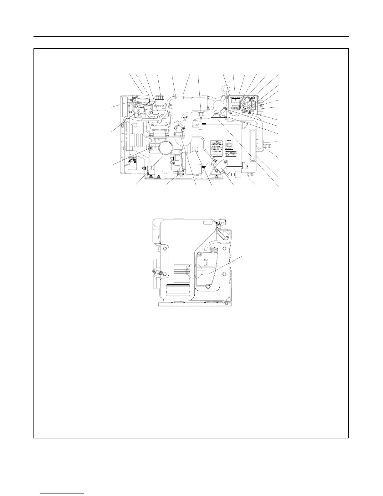
1.7 Service Views
84
22
30 29 2627
34
6
33
1110
16
24
9
18
12
14
23
28
20
ADV-6395-A
GY-250000-A
19
SERVICE VIEW
ENGINE-END VIEW
1
32
3 5 13
17
2
21
7
15
31
1. Electric choke (on carburetor)
2. Carburetor/choke linkage
3. Spark plug (also one on nonservice side)
4. Oil fill
5. Overflow tube
6. Pressure cap (coolant fill location after draining coolant)
7. High water temp. switch
8. Controller
9. Start/Stop switch
10. Nameplate (top)
11. AC load lead connector (nonservice side)
12. Input fuse
13. Battery charging fuse
14. AC circuit breaker
15. Voltage regulator
16. Remote start connector (nonservice side)
17. Voltage regulator fuse
18. Hourmeter
19. Heat exchanger
20. Anticorrosion zinc anode
21. Seawater drain (remove zinc anode)
22. Seawater pump (water inlet)
23. Cooling air inlet
24. High exhaust temp. switch on mixing elbow (nonservice side)
25. Fuel filter (fuel inlet)
26. Fuel feed pump
27. Oil check
28. Coolant drain (remove hose clamp to drain coolant)
29. Oil drain valve
30. Lube oil filter
31. Low oil pressure switch
32. Antidieseling solenoid (on carburetor)
33. Air intake silencer/backfire flame arrestor
34. Coolant overflow bottle (daily coolant check/fill location)
25
Figure 1-1 Service Views
 Loading...