TP-5986 4/0326 Section 7 Generator Troubleshooting
7.1.2 Separate Excitation
By separately exciting the generator to determine the
presence of a faulty voltage regulator, it is possible to
determine if a running fault exists in the rotor and/or
stator. A generator component that appears functional
while static (stationary) may exhibit a running open or
short circuit while dynamic (moving). Centrifugal forces
acting on the windings during rotation or insulation
breakdown as temperatures increase can cause short
circuits.
Note: It is not necessary to separately excite the
generator if there is AC output with flashing
voltage.
Separate Excitation Procedure
1. Disconnect all of the leads from the voltage
regulator.
2. Disconnect the P10 (F1, F2) connector.
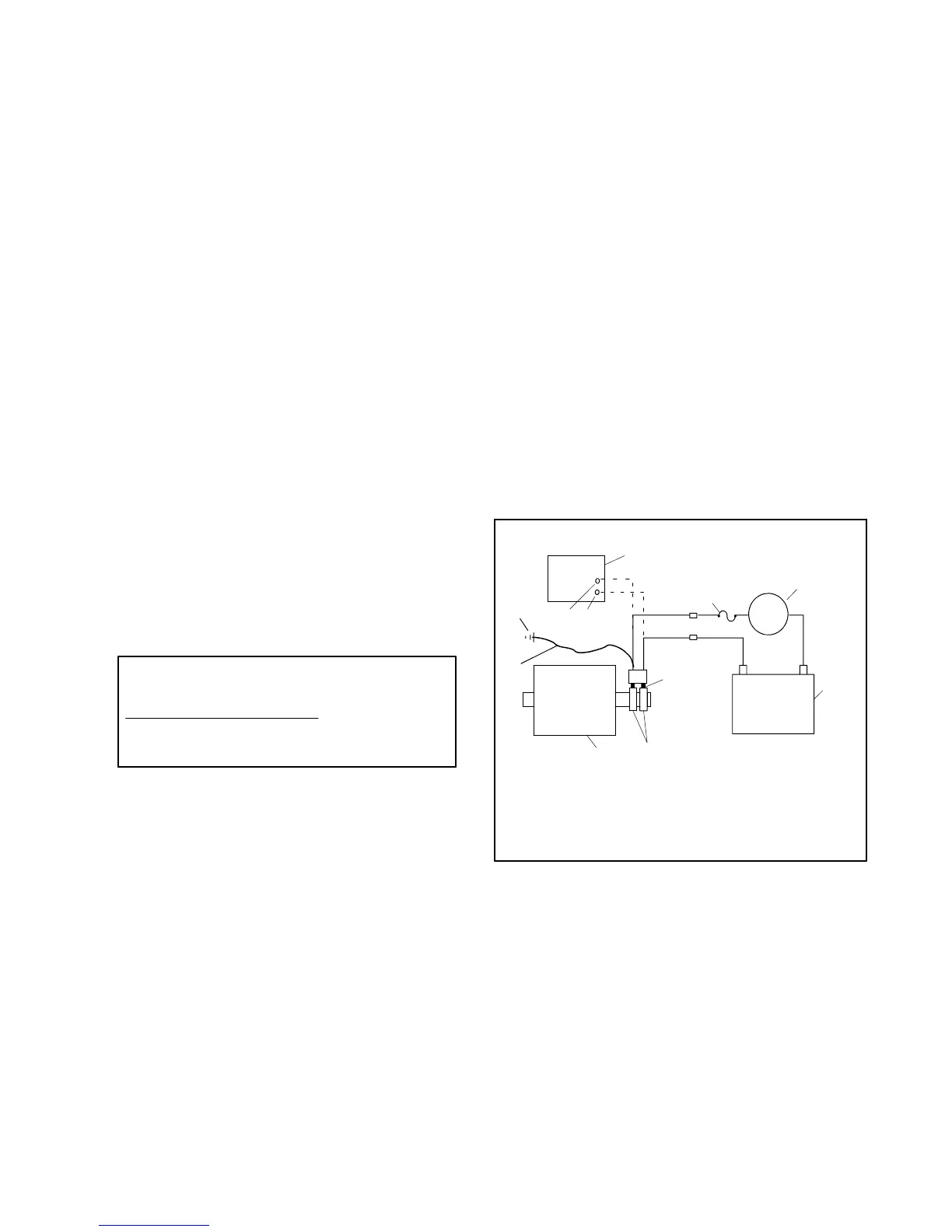
3. Connect a separate excitation circuit as shown in
Figure 7-2. Connect an ammeter and a 10-amp
fuse in series with F1. Note and record the
ammeter reading.
4. The approximate ammeter reading should equal
battery voltage divided by the specified rotor
resistance (cold). See Section 1, Specifications,
for the correct values.
Example:
12 Volts (Battery Voltage)
3.4 Ohms Rotor Resistance
3.5-amp
=
Ammeter reading
5. Start the engine and check that the ammeter
remains stable. An increasing meter reading
indicates a shorted rotor. A decreasing meter
reading to zero, or unstable reading, suggests a
running open in the rotor. If the ammeter is stable,
continue with step 6.
6. With a jumper wire, ground the negative (--) lead
from the rotor to the engine block. An increased
current reading or a fluctuating reading indicates a
grounded rotor winding. Replace the rotor if the
ammeter reading fluctuates. If the ammeter is
stable, continue with step 7.
7. Remove the jumper wire and reverse the
positive (+) and negative (--) leads on the rotor.
Repeat step 5. If the ammeter is stable, ground the
negative (--) lead at its new location on the rotor to
the engine block. Replace the rotor if the ammeter
reading fluctuates.
8. Check for AC output across the stator leads and
compare the measured output to the values in
Section 1, Specifications. If the output varies
considerably from those listed, a faulty stator, rotor,
rectifier module, or armature is likely.
If there is no generator output during normal operation
but output is available when the generator set is
separately excited, the voltage regulator may be
inoperative.
Note: See Section 1, Specifications, for the stator
output voltages (with separately excited
generator). These specifications are based on a
battery voltage of 12 volts. Should the battery
voltage vary, the resulting stator output values will
also vary.
+—
+—
9
8
7
2 3
1
4
5
6
TP-598652
10
11
A
1. Voltage regulator
2. (--) Terminal—(P10-2)
3. (+) Terminal—(P10-1)
4. 10-amp fuse
5. DC ammeter
6. 12-volt battery (DC)
7. Brushes
8. Collector rings
9. Main field (rotor)
10. Jumper lead
11. Engine ground
Figure 7-2 Separate Excitation Connections
 Loading...