TP-5986 4/03 19Section 6 Controller Troubleshooting
Section 6 Controller Troubleshooting
6.1 Sequence of Operation
This section describes the controller sequence of
operation during the generator start, run, stop, and fault
shutdown modes and describes the relay testing
procedures. Use this section as a starting point for
controller fault identification. Use the LEDs on the
controller circuit board to assist in the troubleshooting
process. An illuminated LED indicates that the
respective relay is receiving power; the LED does not
indicate whether that relay is energized or working
properly.
6.1.1 Start
Close the start/stop switch between N and 47 (local or
remote).
The K2 relay energizes and LED2 is illuminated. The
normally-open K2 contacts close to energize the K3
relay (LED3 lights), fuel pump (FP), choke heater
(CHTR), antidiesel solenoid (ADS), ignition (IGN), and
hourmeter (HR).
Flashing of the main field occurs when the K2 contacts
close.
The normally-open K3 contacts close to energize the
K20 relay. The normally-open K20 contacts close,
energizing the starter relay and the starter motor.
Note: The normally-closed LOP contacts open when
the engine builds oil pressure. This may take a
few seconds after engine cranking is initiated.
6.1.2 Run
The bridged rectifier (BR1) receives AC voltage
(12--15 volts) through the B1 and B2 windings of the
stator.
The K1 relay energizes (LED1 lights).
The normally-open K1 contacts close to maintain
voltage to the K2 relay, allowing the function of the fuel
pump (FP), choke heater (CHTR), antidiesel solenoid
(ADS), ignition (IGN), hourmeter (HR), and the remote
panel gauges.
The normally-closed K1 contacts open, ending the
flashing by preventing battery voltage to the main field
(+) and (--).
The K6 relay energizes. The normally-open K6 contacts
close, latching itself on. The normally-closed K6
contacts open, preventing inadvertent starter
engagement by disabling the the K3 relay.
The K3 relay is deenergized (LED3 Off). The K3
contacts open, deenergizing the K20 relay. The K20
contacts open, deenergizing the starter relay and starter
motor.
1
2
3
4
5
6
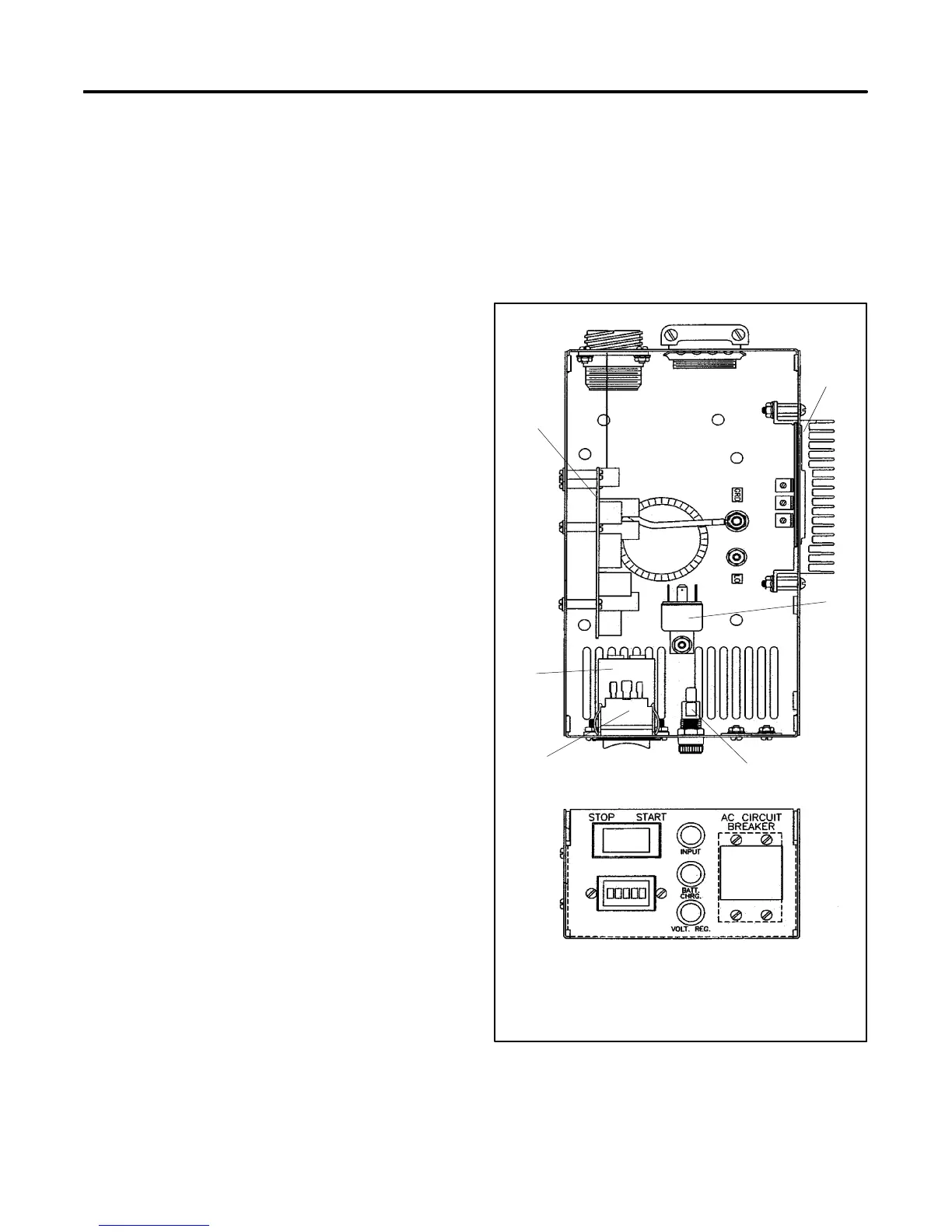
598161
1. Controller circuit board
2. PBIIIE voltage regulator
3. K20 relay
4. Fuses
5. Start/stop switch
6. Hourmeter
Figure 6-1 Controller
 Loading...