23
EFI System
66 690 07 Rev. -- KohlerEngines.com
1. Check mounting and air gap of sensor. It must be
1.5 mm ± 0.25 mm (0.059 in. ± 0.010 in.).
2. Inspect wiring and connections for damage or
problems.
3. Make sure engine has resistor type spark plugs.
4. Disconnect main harness connector from ECU.
5. Connect an ohmmeter between #9 and #10 pin
terminals.
A resistance value of 750-1000 Ω at room
temperature (20°C, 68°F) should be obtained. If
resistance is correct, check mounting, air gap,
toothed ring gear (damage, runout, etc.), and
fl ywheel key.
6. Disconnect speed sensor connector from wiring
harness. It is connector with one heavy black lead.
Viewing connector as shown (dual aligning rails on
top), test resistance between terminals indicated. A
reading of 750-1000 Ω should again be obtained.
7. If resistance is incorrect, remove screw securing
sensor to mounting bracket and replace sensor.
a. If resistance in step 5 was incorrect, but
resistance of sensor alone was correct, test main
harness circuits between sensor connector
terminals and corresponding pin terminals in main
connector. Correct any observed problem,
reconnect sensor, and perform step 5 again.
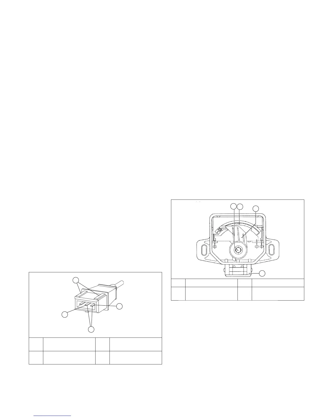
Throttle Position Sensor (TPS)
A
C
B
D
A Throttle Valve Shaft B Resistor Track
C
Wiper Arm with
Wiper
D
Electrical
Connection
TPS is a sealed, non-serviceable assembly. If diagnosis
indicates a bad sensor, complete replacement is
necessary. If a blink code indicates a problem with TPS,
it can be tested as follows:
1. Counting number of turns, back out idle speed
adjusting screw (counterclockwise) until throttle
plates can be closed completely.
2. Disconnect main harness connector from ECU, but
leave TPS mounted to throttle body/manifold.
3. Connect Red (positive) ohmmeter lead to #8 pin
terminal, and Black (negative) ohmmeter lead to #4
pin terminal. Hold throttle closed and check
resistance. It should be 800-1200 Ω.
a. Turn key switch to ON/RUN position. Fuel pump
will run for about three seconds and stop. Turn
switch off and back on to restart fuel pump.
Repeat this procedure until fuel pump has cycled
fi ve times, then start engine.
3. System can also be primed similar to relieving
pressure.
a. Connect pressure gauge as described above for
relieving fuel pressure. Depress and hold release
button and crank engine until air is purged and
fuel is visible in discharge tube. If fuel is not
visible after 10 seconds, stop cranking and allow
starter to cool for 60 seconds.
Priming Without a Test Valve in Fuel Rail
NOTE: Number of cranking intervals necessary will
depend on individual system design, and/or
when system has been disassembled.
1. Crank engine in 10-15 second intervals, allowing a
60 second cool-down period between cranking
intervals, until engine starts.
ELECTRICAL COMPONENTS
A 32 pin (MSE 1.1) plastic-cased ECU is used on these
engines.
Never attempt to disassemble ECU. It is sealed to
prevent damage to internal components. Warranty is
void if case is opened or tampered with in any way.
All operating and control functions within ECU are
preset. No internal servicing or readjustment may
be performed. If a problem is encountered, and you
determine ECU to be faulty, contact your source
of supply. Do not replace ECU without factory
authorization.
Relationship between ECU and throttle position sensor
(TPS) is very critical to proper system operation. If TPS
or ECU is changed, or mounting position of TPS is
altered, applicable TPS Initialization Procedure must be
performed to restore synchronization.
ENGINE SPEED SENSOR
Speed Sensor Circuit
A
D
C
B
A
Corresponds To #10
In Main Connector.
B Dual Aligning Rails
C
Corresponds To #9
In Main Connector.
D Test Terminals
Engine speed sensor is a sealed, non-serviceable
assembly. If Fault Code diagnosis indicates a problem
within this area, check and test as follows.
 Loading...