4124 690 06 Rev. J KohlerEngines.com
Electrical System
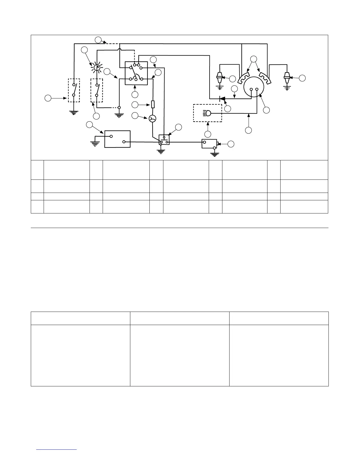
Wiring Diagram-3 Amp Unregulated Battery Charging System/70 Watt Lighting
K
C
B
L
F
H
A
J
G
O
S
N
D
M
T
I
E
P
S
R
Q
A
R
S
B
A
Optional Oil
Sentry
™
Switch
(Shutdown)
B 12 V. Battery C
Optional Oil
Sentry
™
Switch
(Indicator Light)
D Light E
Ground-To-Kill
Lead (White)
F Ground G
Optional
Ammeter
H Optional Fuse I Key Switch J Red
K Blue L Solenoid M Lights N Starter O Yellow
P Diode Q
3 Amp/70 Watt
Flywheel Stator
R Black S Spark Plug(s) T Ignition Modules
Electronic Ignition Systems Tests
NOTE: Ignition tester must be used to test ignition on these engines. Use of any other tester can result in inaccurate
ndings. Battery on unit must be fully charged and properly connected before performing tests (a battery that
is hooked up or charged backward will crank engine but it won’t have spark). Be certain drive is in neutral and
all external loads are disconnected.
Test Ignition Systems
NOTE: If engine starts or runs during testing, you may need to ground kill lead to shut it down. Because you have
interrupted kill circuit, it may not stop using switch.
Isolate and verify trouble is within engine.
1. Locate connectors where wiring harnesses from engine and equipment are joined. Separate connectors and
remove white kill lead from engine connector. Rejoin connectors and position or insulate kill lead terminal so it
cannot touch ground. Try to start engine to verify whether reported problem is still present.
Condition Possible Cause Conclusion
Problem goes away. Electrical System Check key switch, wires, connections,
safety interlocks, etc.
Problem persists. Ignition or Electrical System Leave kill lead isolated until all testing
is completed.
Identify white kill lead of engine
wiring harness connector. Establish
a connection to a known good
ground location. Engine should kill
completely. If not or only one cylinder
is affected, test ignition modules and
white kill lead connection for affected
DSAI module (DSAI only).
 Loading...


