8 mm Governor Lever and Hole Position/RPM Chart for CH20-CH740 Engines
Governor Shaft
Conguration
Intended Maximum RPM
Non-Accelerator Pump
Carburetor
Accelerator Pump Carburetor
High Idle WOT Spring Color Hole No. Spring Color Hole No.
Needle Bearing
3744 3600 Orange 2 - -
3120 3000 Clear 1 - -
Standard
(Parent Material)
3888 3600 Red 4 Purple 3
3780 3500 Purple 3 Black 3
3672 3400 Black 3 Red 3
3564 3300 Red 3 Orange 2
3456 3200 Purple 2 Blue 2
3348 3100 Blue 2 Orange 1
3240 3000 Orange 1 Black 1
3132 2900 Clear 2 Red 1
3024 2800 Red 1 Clear 1
8 mm Governor Lever and Hole Position/RPM Chart for CH750 Engines
Governor Shaft
Conguration
Intended Maximum RPM With Governed Idle System
High Idle WOT Spring Color Hole No.
Standard
(Parent Material)
3888
3780
3672
3564
3456
3348
3600
3500
3400
3300
3200
3100
Blue
Purple
Orange
Green
Black
Red
3
2
1
1
1
1
Install Control Panel (if equipped)
1. Install panel to blower housing.
2. Connect throttle control cable or shaft.
3. Connect choke control cable to control bracket.
4. Connect Oil Sentry
™
indicator light wires.
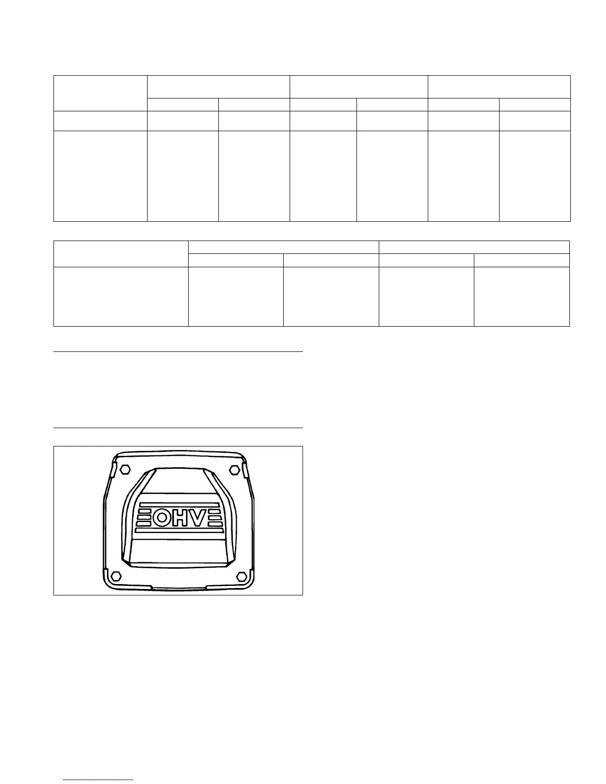
Install Valve Covers
Torque Sequence
1
2
3
4
NOTE: Do not scrape old RTV sealant (if used) off
sealing surface of cylinder head as this could
cause damage and result in leaks. Use of gasket
remover solvent (paint remover) is
recommended.
NOTE: Second fastener may secure fuel pump bracket
on earlier models.
Three valve cover designs have been used. First type
used a gasket and RTV sealant between cover and
sealing surface of cylinder head. Second type had a
black O-ring installed in a groove on underside of cover
and may have metal spacers in bolt holes. Latest design
uses a yellow or brown O-ring, with bolt hole spacers
molded in place. Tightening torque differs between
gasket and O-ring style covers. Kits are available for
converting to latest O-ring type covers. Differences are
pointed out in following installation steps.
1. If using gasket or sealant type cover, prepare sealing
surfaces of cylinder head and cover, refer to Tools
and Aids for approved sealants. Always use fresh
sealant. Using outdated sealant could result in
leakage. With O-ring type covers, make sure sealing
surfaces are clean.
2. Make sure there are no nicks or burrs on sealing
surfaces.
3. For covers requiring RTV sealant, apply a 1.5 mm
(1/16 in.) bead to sealing surface of both cylinder
heads, install a new cover gasket on each, then
apply a second bead of sealant on top surface of
gaskets. For O-ring type covers, install a new O-ring
in groove of each cover. Do not use gaskets or RTV
sealant.
4. Locate cover with oil ll neck on same side as
removed and install lifting strap in original position.
With O-ring type covers, position cover on cylinder
head. If loose spacers were used, insert a spacer in
each screw hole. On both types, install four screws
in each cover and nger tighten.
5. Torque valve cover fasteners to proper specication
using sequence shown.
Reassembly
8724 690 06 Rev. J KohlerEngines.com
 Loading...


