62
Disassembly/Inspection and Service
KohlerEngines.com 24 690 06 Rev. J
2. One-barrel carburetor models only: Remove
carburetor mounting screws.
Two-barrel carburetor models only: If required use
nuts locked together and remove carburetor
mounting studs on starter side of intake manifold
and one stud on oil lter side.
Pivot carburetor to clear breather cover tting and
pressure switch (if equipped). Remove carburetor,
throttle linkage, choke linkage, and governor lever as
an assembly.
3. Remove carburetor, throttle linkage and governor
lever as an assembly.
4. Remove carburetor gasket.
5. If necessary, carburetor, throttle linkage and
governor lever can be separated. Reattach bushings
to linkage following separation to avoid losing them.
Remove Oil Sentry
™
(if equipped)
1. Disconnect lead from Oil Sentry
™
switch.
2. Remove Oil Sentry
™
switch from breather cover.
Remove Electric Starter Motor
1. Disconnect leads from starter.
2. Remove screws.
3. Remove starter assembly and any spacers (if used).
Remove Outer Bafes and Blower Housing
1. Disconnect plug from rectier-regulator on blower
housing.
2. Use tip of dipstick or a similar small at tool to bend
locking tang, then remove B+ (center lead) from
terminal plug as shown. This will allow blower
housing to be removed without disturbing wiring
harness.
3. Rectier-regulator does not have to be detached
from blower housing. If engine is equipped with
SMART-SPARK
™
SAM module should be removed
from cylinder bafe or blower housing. Module will
hang loose as part of wiring harness.
4. Remove screws securing outer bafes. Note location
of any lifting strap and position of two short screws
(one each side on bottom) for reassembly.
5. Remove outer bafes on both sides.
6. On engines equipped with a metal debris screen,
remove screen before removing blower housing.
Plastic debris screens can be removed after blower
housing is removed.
7. Remove lower blower housing screw and washer
securing rectier-regulator ground lead or grounding
strap.
8. Two-barrel carburetor models only: Remove screws
securing debris shield to blower housing. Wiring
harness is attached to underside of shield.
9. Remove remaining screws and detach blower
housing.
10. Disconnect plug from key switch in blower housing if
engine is equipped.
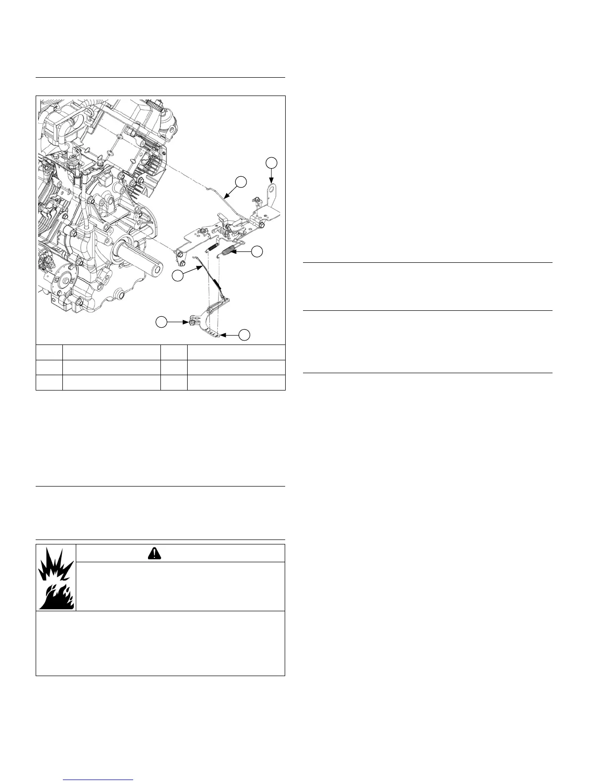
Remove Throttle and Choke Controls
Control Bracket Components
E
F
D
C
B
A
A Choke Linkage B Control Bracket
C Spring D Governor Lever
E Nut F Throttle Linkage
1. Remove screws securing control bracket and rear air
cleaner bracket (some models) to cylinder heads.
2. Mark spring hole locations and disconnect spring
from governor lever.
3. Remove choke linkage from choke actuator lever
and carburetor.
Remove External Governor Controls
Loosen nut and remove governor lever from cross shaft.
Leave lever attached to throttle linkage and lay assembly
on top of crankcase.
Remove Carburetor
WARNING
Explosive Fuel can cause res and severe
burns.
Do not ll fuel tank while engine is hot or
running.
Gasoline is extremely ammable and its vapors can
explode if ignited. Store gasoline only in approved
containers, in well ventilated, unoccupied buildings,
away from sparks or ames. Spilled fuel could ignite
if it comes in contact with hot parts or sparks from
ignition. Never use gasoline as a cleaning agent.
1. Disconnect fuel shut-off solenoid lead and ground
lead, if equipped.
 Loading...


