24
Governor System
KohlerEngines.com 14 690 01 Rev. G
Governed speed setting is determined by position of
throttle control. It can be variable or constant, depending
on engine application.
Governor is designed to hold engine speed constant
under changing load conditions. Most engines are
equipped with a centrifugal yweight mechanical
governor. Governor gear/yweight mechanism of
mechanical governor is mounted inside crankcase and is
driven off gear on camshaft.
This governor design works as follows:
● Centrifugal force acting on rotating governor gear
assembly causes yweights to move outward as
speed increases. Governor spring tension moves
them inward as speed decreases.
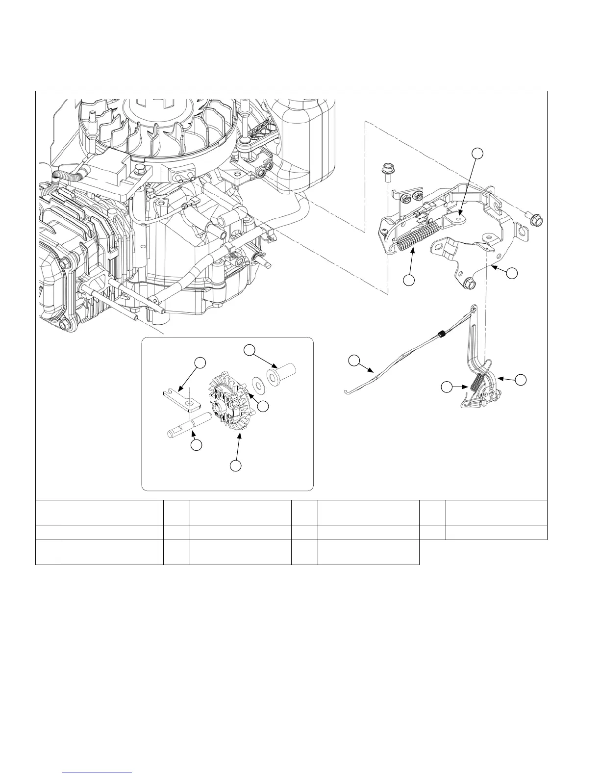
GOVERNOR
Governor Components
E
C
D
I
J
F
A
B
G
K
H
A Control Spring B
Intermediate Control
Lever
C Control Bracket D Governor Lever
E Compression Spring F Linkage G Regulating Pin H Flyweight(s)
I Governor Gear J Governor Gear Shaft K
Governor Shaft
Retainer
● As yweights move outward, they cause regulating pin
to move outward.
● Regulating pin contacts tab on cross shaft causing
shaft to rotate.
● One end of cross shaft protrudes through crankcase.
Rotating action of cross shaft is transmitted to throttle
lever of carburetor through external throttle linkage.
● When engine is at rest, and throttle is in fast position,
tension of governor spring holds throttle plate open.
When engine is operating, governor gear assembly is
rotating. Force applied by regulating pin against cross
shaft tends to close throttle plate. Governor spring
tension and force applied by regulating pin balance
each other during operation, to maintain engine
speed.
 Loading...