38 Section 3 Decision-Makerr 3+ Troubleshooting TP-6356 4/12
20
21
6
19
321
18 16 131517 11
5
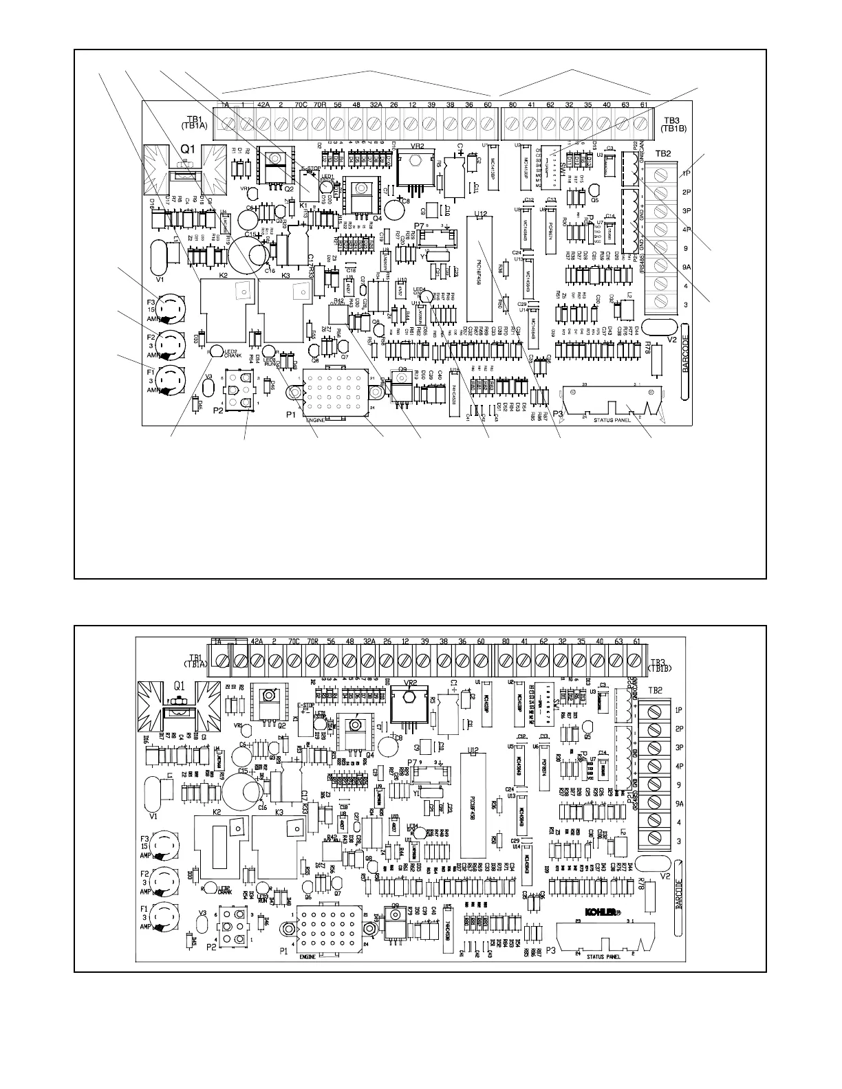
GM28725-D
4
8
7
9
10
14 12
1. K2 relay: control relay (crank)
2. K3 relay: control relay (run/fuel)
3. K1 relay: emergency stop
4. LED1 (emergency stop)
5. TB1 (TB1A) terminal strip
6. TB3 (TB1B) terminal strip
7. DIP switches
8. TB2 terminal strip
9. P22 for CAN (engine) communication
connection
10. P21 for Modbus RS-485 communication
connection
11. P3 connector (control panel harness) to P4
(LED indicator panel circuit board)
12. Microprocessor chip
13. LED4 (overvoltage)
14. R42 overvoltage adjustment
15. P1 connector (DC harness)
16. LED3 (K3 relay)
17. P2 connector (AC harness)
18. LED2 (K2 relay)
19. Fuse: 3 amp (F1) remote annunciator,
battery positive (+) 42A connection
20. Fuse: 3 amp (F2) controller
21. Fuse: 15 amp (F3) engine and
accessories
Figure 3-2 16-Light Controller Circuit Board GM28725 (Red Board) Components
GM64497-G
Figure 3-3 16-Light Controller Circuit Board GM64497 (Blue B oard) Components (same as GM28725 except for
U12 microprocessor)
 Loading...


