39Section 3 Decision-Makerr 3+ TroubleshootingTP-6356 4/12
Emergency
Stop
B+
B--
Emergency Stop
Auxiliary
Overcrank
Overspeed
Low Oil Pressure
High Coolant Temperature
Common Fault /Prealarm (Line 1, 32)
Low Coolant Temperature
System Ready
Not In Auto
Pre High Coolant Temperature
Pre Low Oil Pressure
Low Fuel
Battery Charger Fault
Low Battery Volts
(--)
Common Fault Indicator A ctivated by:
High Coolant Temperature (32, 32A)
Pre High Coolant Temp. (32)
Low Oil Pressure (32, 32A)
Pre Low Oil Pressure (32)
Low Coolant Temperature (32)
Overcrank (32, 32A)
Overspeed (32, 32A)
Low Fuel (32)
Auxiliary (32)
Emergency Stop (32A)
Connect A / V Alarm or
Common Fault Relay K it
Running Mode
Cool-Down Mode
(--)
Common Fault/Prealarm (Line 2, 32A )
Prime Power Operation
Crank Mode
Remote Switch
GM28725-D-S
TB1-2
TB2-8
P1--2
P1--5
P1--6
P2--6
P3--1
Battery
P1-12
F3
K2
K3
P1-4 Alternator Flash
P1-1 Crank (71)
P1-3 Safeguard B+, Engine ECM, Governor
P1-7 Engine Run, Fuel Solenoid or Engine Ignition
F2
12V Reg.
Q2
Logic
K1
K2
K3
Logic
Logic
K1
Logic
K1
TB1--1A
P1--8
P3--11
F1
TB1--42A
--+
K20
Starter Motor
P2-1 Gauges
Low Battery Volts (62)
TB3-62 Input
P3-12 Output
Battery Charging Fault ( 61)
P3-10 Output
Low Fuel (63)
TB3-63 Input
P3-8 Output
Common Alarm (32)
TB3-32 Output
P3-6 Input
Pre High Coolant Temp. (40)
P1-16 Input
TB3-61 Input
P3-23 Output
TB3-40 Output
Low Water Temperature (35A)
P1--24 Input
TB3-35A Output
P3-18 Output
K1
TB1--48
P3--21
Logic
Emergency Stop (48)
PreLow Oil Pressure (41)
P1--23 Input
TB3-41 Output
P3-16 Output
TB2-6
(2)
(S2)
(3)
(9A)
(1)
(N)
(2)
(Ribbon
Connector)
TB1 (TB1A) TB3 (TB1B)
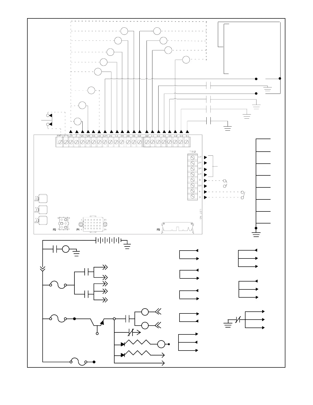
Figure 3-4 Controller Circuit Board GM28725/GM64497 Connections TB1 (TB1A), TB3 (TB1B), and TB2
 Loading...


