75
Reassembly
32 690 03 Rev. E KohlerEngines.com
Install Valve Covers
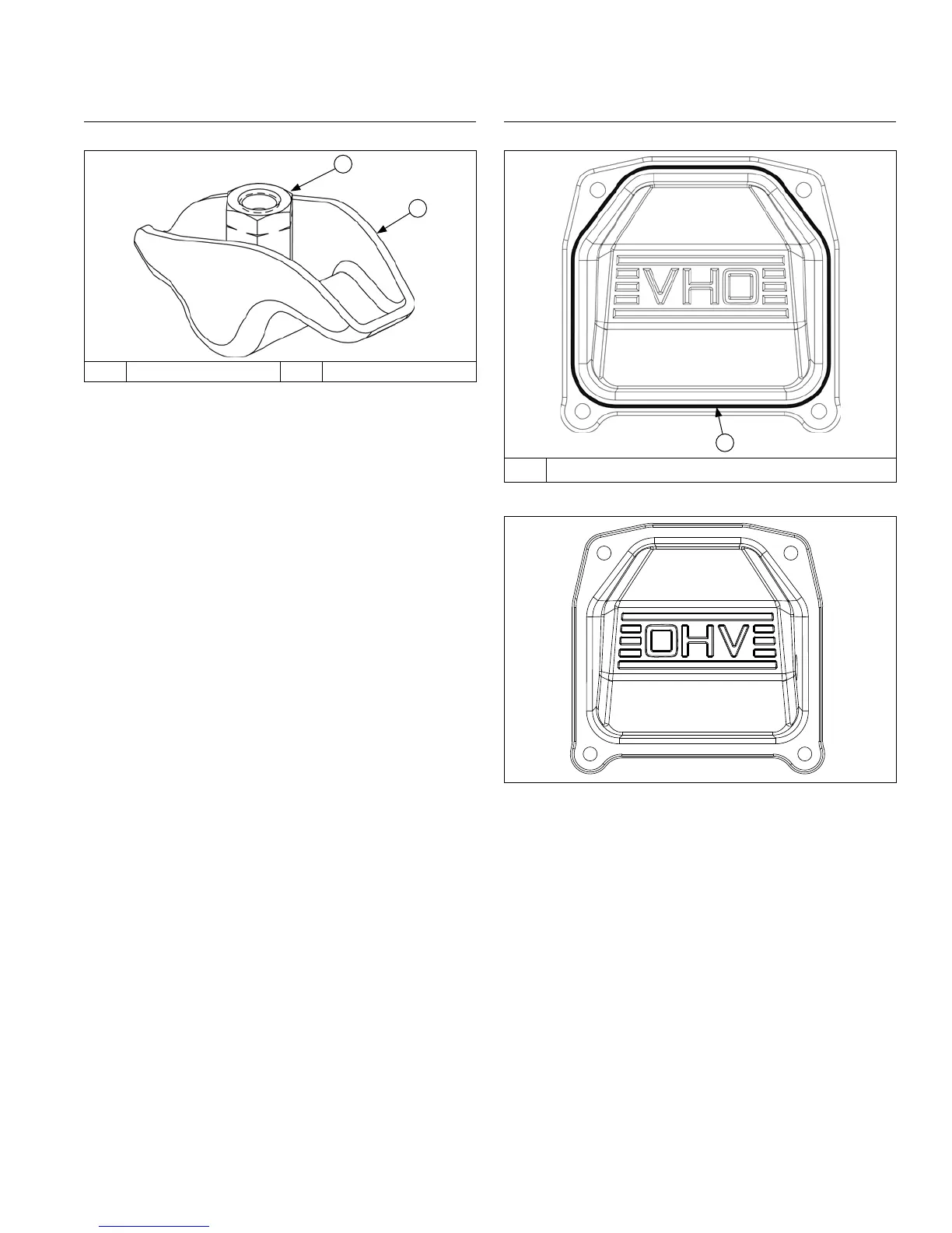
Valve Cover RTV Sealant
A
A RTV Sealant
Valve Cover Torque Sequence
1&5 3
2
4
NOTE: Always use fresh sealant. Using outdated
sealant can result in leakage. Refer to Tools and
Aids for information on sealant dispenser.
NOTE: To ensure proper adhesion of sealant to both
sealing surfaces, perform step 3 immediately (5
minutes maximum) after application of RTV.
RTV silicone sealant is used as a gasket between valve
cover and cylinder head. Refer to Tools and Aids for a
listing of approved sealants.
1. Prepare sealing surfaces of cylinder heads and
valve covers. Flatness of sealing surface must be
checked prior to reinstallation. See Disassembly.
2. Apply a 1.5 mm (1/16 in.) bead of sealant to valve
cover as shown.
3. Position covers on cylinder heads. If a pulse style
fuel pump is used valve cover with pulse tting hole
must be installed on side 2. Install screws in each
cover and nger tighten.
4. Torque valve cover fasteners to 9.6 N·m (85 in. lb.),
using sequence shown.
Adjust Valve Clearance
Adjusters Retaining Push Rods
A
B
A Adjuster B Rocker Arm
1. Rotate crankshaft to establish TDC on compression
stroke for cylinder 1.
Check for:
a. Compression will be felt through spark plug hole.
b. Keyway of crankshaft will be aligned with cylinder
1.
c. No rocker arm/push rod movement if crankshaft
is rotated slightly back and forth. If they are
moving, rotate crankshaft 1 full revolution.
2. Insert a 0.127 mm (0.005 in.) feeler gauge between
end of 1 valve and rocker arm. Turn adjuster until a
slight drag is felt. Hold in this position and tighten
setscrew securely. Torque setscrew to 7.9 N·m
(70 in. lb.). After tightening recheck adjustment.
Proper valve clearance is 0.101/0.152 mm
(0.004/0.006 in.).
3. Repeat procedure for other valve on side 1.
4. Viewed from PTO end, rotate crankshaft 270° (3/4
turn) counterclockwise and align crankshaft keyway
with cylinder 2, which now puts cylinder at TDC on
compression stroke.
5. Repeat steps 3-4 for setting valve clearance on side
2.
6. Rotate crankshaft to check for free operation of
valve train. Check for clearance between valve
spring coils at full lift, or bending of push rod(s) can
occur. Minimum allowable clearance is 0.25 mm
(0.010 in.).
Check Assembly
Rotate crankshaft a minimum of 2 revolutions to check
longblock assembly and overall proper operation.
 Loading...