TP-6807 12/1112 Section 1 Description
Loads. The transfer switch can be connected to supply
all of the electrical loads in the home, or only the
essential loads such as the furnace, refrigerator, well
pump, and selected light circuits. Identify the essential
circuits that must be supplied during a power outage.
Verify that the generator set and transfer switch are
adequately rated to supply all of the selected loads.
Circuit breakers. Because the size and number of
circuit breakers required will vary with each application,
circuit breakers are not provided with the transfer switch
load center.
Determine the circuits that will be connected to the
transfer switch (essential loads). Identify the breakers
for those circuits in the main distribution panel.
The ATS load center requires Square D type QO
breakers. If the main distribution panel uses the same
type of breakers, the breakers can be moved from the
main panel to the load center. Otherwise, obtain new
Square D type QO circuit breakers. For each circuit, the
rating of the load center circuit breaker must match the
rating of the existing breaker in the main panel.
Up to 8 tandem breakers can be used. Use Square D
type QOT tandem breakers.
Verify that the total rating for all of the breakers used in
the load center does not exceed the rating of the transfer
switch.
1.4 Controller Interface Board
All ATS control functions are performed by the
RDC2/DC2 controller mounted on the generator set and
communicated through the interface board. The
controller interface board sends voltage sensing data to
the RDC2/DC2 controller and receives transfer and load
control signals from the RDC2/DC2 controller.
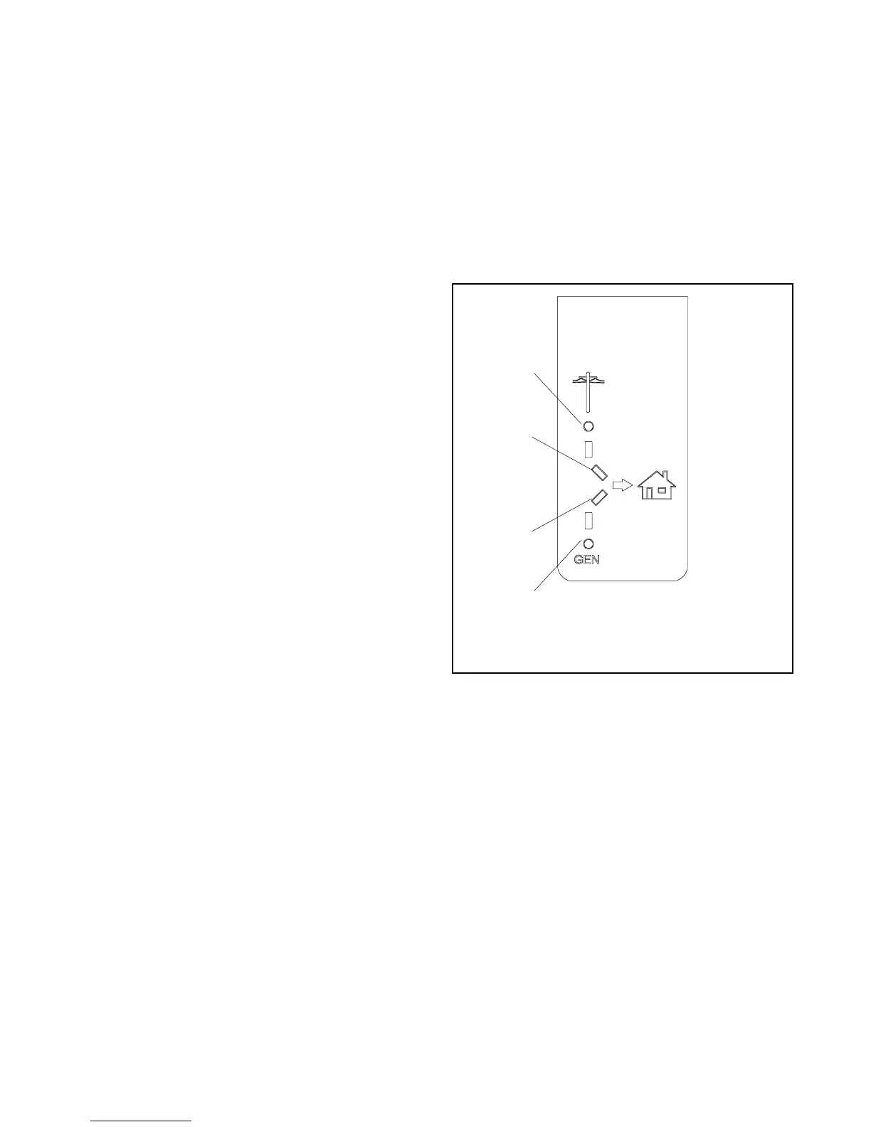
1.5 Optional LED Indicator Panel
A user interface panel that contains status-indicating
LEDs is available. See Figure 1-3. Source available
LEDs light to indicate that the utility and/or generator
sources are available. The utility or generator source
supplying load LED lights to show which source is
connected to the building load (i.e. contactor position,
normal or emergency).
If the status indicator is purchased as a loose kit (not
factory-installed), refer to the installation instructions
provided with the kit, TT-1585.
1
GM78649
1. Utility power available
2. Utility source supplying load
3. Generator source supplying load
4. Generator power available
2
3
4
Figure 1-3 LED Indicators
 Loading...


