TP-6807 12/1118 Section 2 Installation
2.5.3 Neutral Connection
Connect the neutral from the main panel to the neutral
lug in the ATS enclosure.
Ground the system according to NEC and local codes.
2.5.4 Neutral Bonding Jumper, Service
Entrance Models
The transfer switch is shipped with the
neutral-to-ground jumper installed. For non-service
entrance applications, disconnect the neutral-to-ground
bonding jumper. See the transfer switch dimension
drawing.
2.5.5 Engine Start Function
The engine start function is controlled by the RDC2/DC2
controller on the generator set. There are no engine
start terminals on the Model RXT ATS.
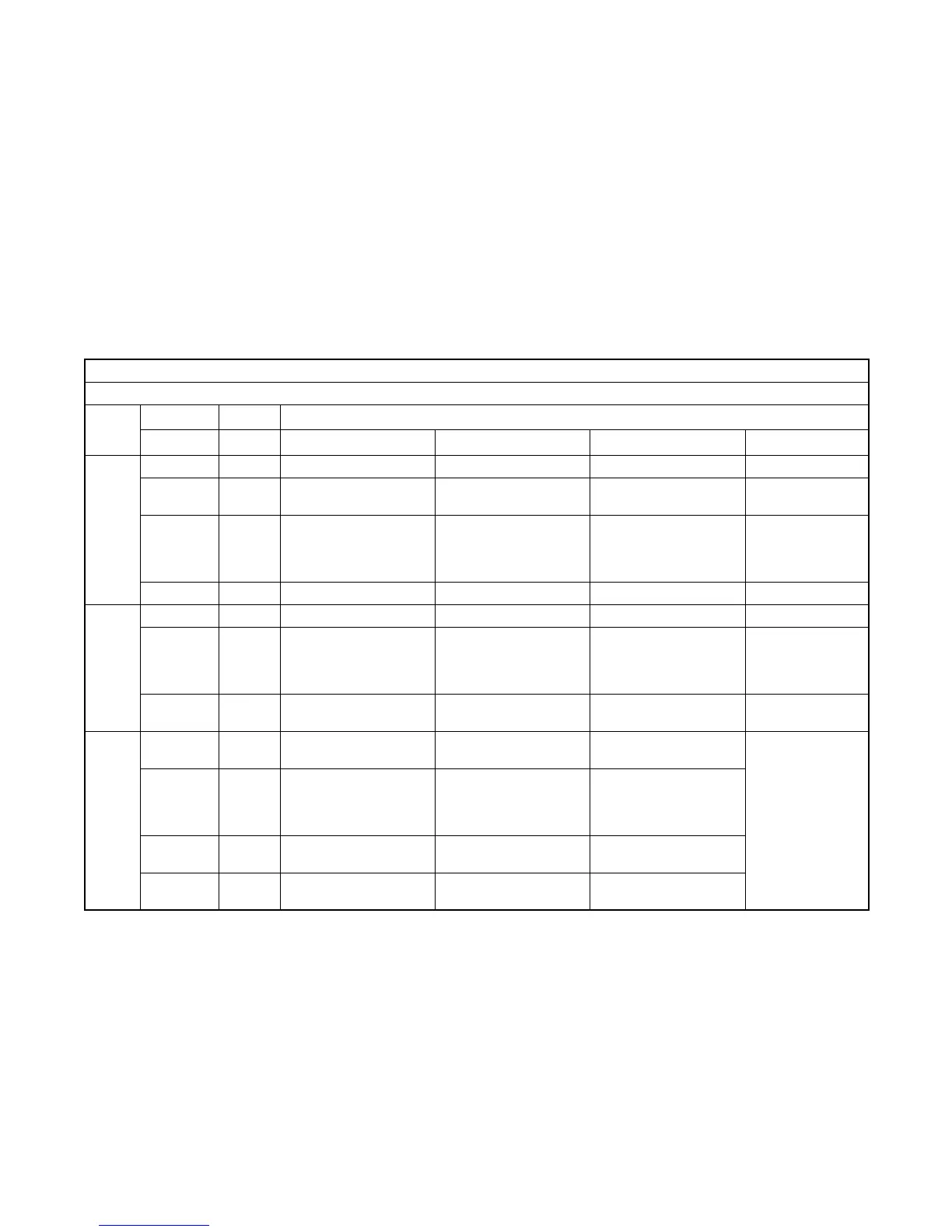
Cable Sizes
AL/CU UL-Listed Solderless Screw-Type Terminals for External Power Connections
Switch
Size,
Amps
Range of Wire Sizes, Cu/Al
Switch Phases Normal and Emergency Load Neutral Ground
100
Standard 1 (1) #14 -- 1/0 AWG (1)#14–1/0AWG (3)#12–1/0AWG (9)#4–14AWG
With load
center
1 (1)#14–1/0AWG
per customer-supplied
circuit breaker
(1)#2–2/0AWG (9)#4–14AWG
Service
Entrance
1
Normal: (1) #12 – 2/0
AWG
Emerg: (1) #6 – 250
MCM
(1) #6 – 250 MCM (3) #6 – 250 MCM (3)#14–1/0AWG
3-Phase 3 (1)#8–3/0AWG (1)#8–3/0AWG (3)#6AWG–3/0AWG (3)#6–3/0AWG
200
Standard 1 (1) #6 AWG – 250 MCM (1) #6 AWG – 250 MCM (3) #6 AWG – 250 MCM (9)#4–14AWG
Service
Entrance
1
Normal: (1) #4 – 300
MCM
Emerg: (1) #6 -- 250
MCM
(1) #6 AWG – 250 MCM (3) #6 AWG – 250 MCM (3)#14–1/0AWG
3-Phase 3 (1) #6 AWG – 250 MCM (1) #6 AWG – 250 MCM
(3) #4 AWG – 600 MCM
(6) 1/0 – 250 MCM
(3)#6–3/0AWG
400
Standard 1 (2) #6 – 250 MCM (2) #6 – 250 MCM
(1) #4 – 600 MCM
(2) 1/0 – 250 MCM
(3)#14–1/0AWG
Service
Entrance
1
Normal: (2) 3/0 – 250
MCM
Emerg: (2) #6 -- 250
MCM
(2) #6 – 250 MCM
(3) #4 – 600 MCM
(6) 1/0 – 250 MCM
3-pole
208-240 V
3 (2) #6 – 250 MCM (2) #6 – 250 MCM
(1) #4 – 600 MCM
(2) 1/0 – 250 MCM
3 or 4 pole
480 V
3
(1) #4 – 600 MCM
(2) #6 – 250 MCM
(1) #4 – 600 MCM
(2) #6 – 250 MCM
(1) #4 – 600 MCM
(2) 1/0 – 250 MCM
Figure 2-8 Cable Sizes
 Loading...


