TP-6807 12/1116 Section 2 Installation
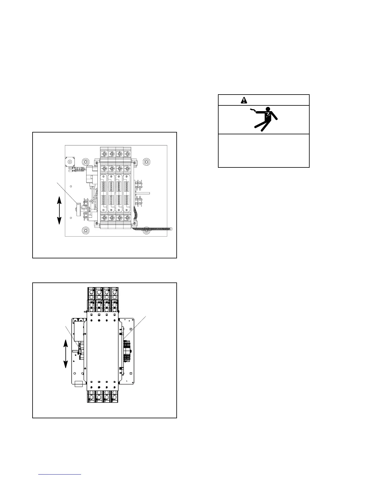
2. Insert the maintenance handle or a tool (such as a
screwdriver) into the hole in the shaft on the left
side of the operator as shown in Figure 2-6 or
Figure 2-7.
3. Move the maintenance handle (or tool) up or down
as shown to manually operate the transfer switch. It
should operate smoothly without any binding. If it
does not, check for shipping damage or
construction debris.
4. Return the transfer switch to the Normal position.
5. Remove the maintenance handle and return it to the
storage location.
1. Insert handle or tool here for manual operation
GM78867
1
Figure 2-6 Manual Operation, 100--200 Amp
3-Phase Switches
tp6225
1
2
1. Handle storage location
2. Insert handle here for manual operation
Figure 2-7 Manual Operation, 400 Amp 3-Phase
Switches
2.5 Electrical Wiring
Refer to the connection diagrams on the transfer switch
enclosure door and the wiring diagrams in Section 6
during installation.
All wiring must comply with applicable national, state,
and local electrical codes. Use separate conduit for AC
power wiring and low-voltage DC, control, and
communication system wiring.
Hazardous voltage.
Will cause severe injury or death.
Disconnect all power sources before
opening the enclosure.
DANGER
Making line or auxiliary connections. Hazardous voltage
can cause severe injury or death. To prevent electrical
shock deenergize the normal power source before making any
line or auxiliary connections.
Grounding electrical equipment. Hazardous voltage can
cause severe injury or death. Electrocution is possible
whenever electricity is present. Ensure you comply with all
applicable codes and standards. Electrically ground the
generator set and related equipment and electrical circuits.
Turn off the main circuit breakers of all power sources before
servicing the equipment. Never contact electrical leads or
appliances when standing in water or on wet ground because
these conditions increase the risk of electrocution.
2.5.1 Load Center Circuit Breakers
The 100 amp Model RXT transfer switch is available
with a built-in load center with room for up to 16
single-pole circuit breakers. Up to 8 tandem breakers
can be used for a maximum of 24 circuits.
The load center uses Square D type QO or QOT tandem
breakers. In an essential load application, the breakers
can be moved from the main panel to the load center if
the main distribution panel uses the same type of
breakers. Otherwise, obtain and install new Square D
type QO circuit breakers. The rating of the load center
circuit breaker must match the rating of the existing
breaker in the main panel for each circuit. If circuit
breakers are removed from the load panel, install cover
plates over the vacant positions. Cover plates can be
obtained from a local Square D supplier.
Verify that the total rating for all breakers used in the load
center does not exceed the rating of the transfer switch.
 Loading...


