TP-6807 12/1120 Section 2 Installation
2.5.7 Optional Load Control Connection
Connector P11 on the interface module provides a
connection point for optional load control circuits. The
load control contact provides a delayed contact closure
to allow startup of selected loads 5 minutes after transfer
to the emergency power source (generator set). Use
this contact to delay startup of equipment with large
motor-starting loads such as air conditioners.
See Figure 2-11 for the location of load control
connector P11. See Figure 2-12 for contact ratings,
connection, and wire size information.
Note: An optional load control module is available for
generator sets equipped with the RDC2 or DC2
controller. The load control module allows
management of up to six separate loads (two
HVAC thermostat connections and four other
non-essential loads). See TT-1574, Load Control
Module Instructions.
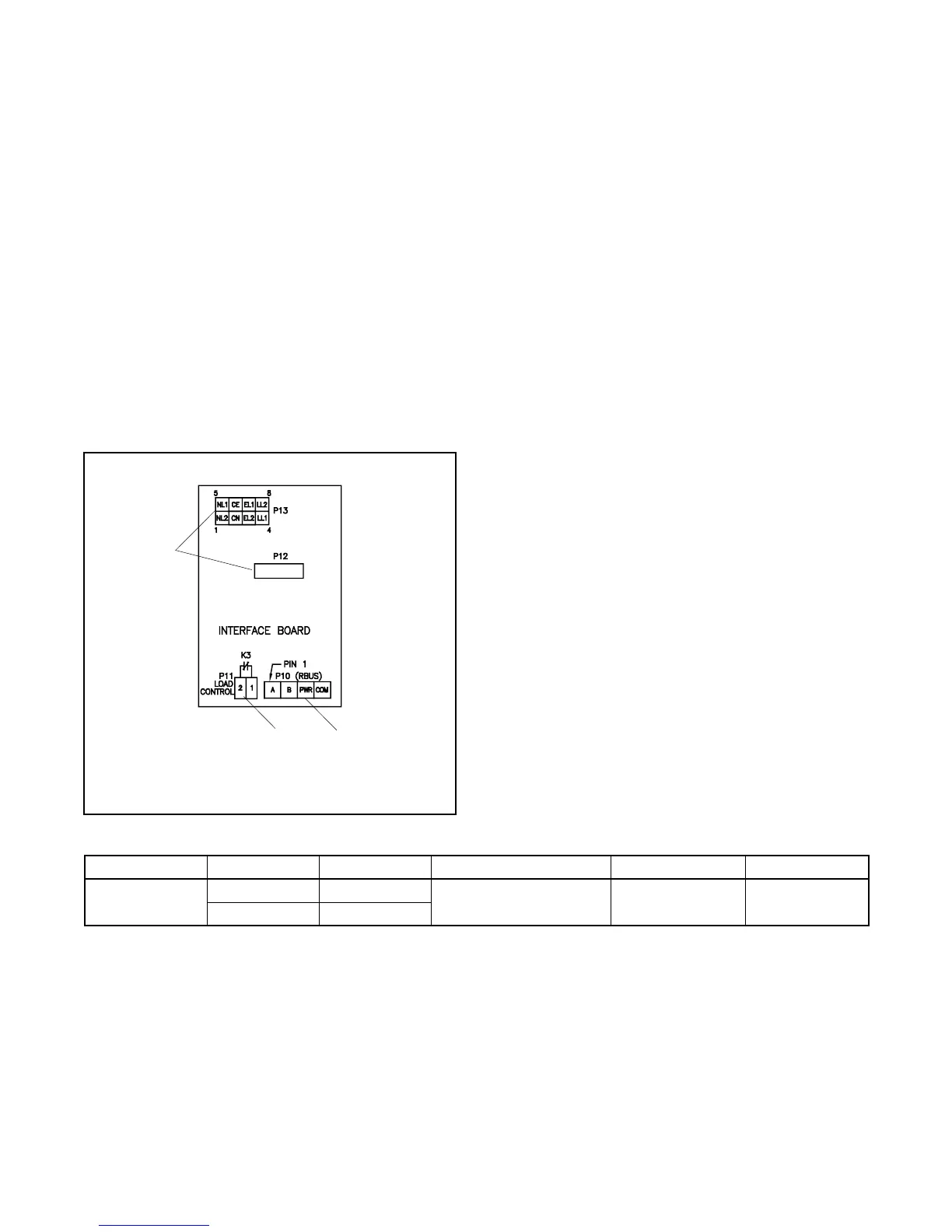
1. ATS/generator set interface connection P10
2. Load control connection P11
3. Factory connections
1
GM80663
2
3
Figure 2-11 Interface Module Connections
2.5.8 Accessory Module Connections
For connection of the optional load control module
(LCM) or programmable interface module (PIM), refer to
the instructions provided with the modules and to the
generator set installation manual.
2.6 Test and Exercise
Refer to the generator set Operation Manual for
instructions to test the power system operation and to
set the RDC2 or DC2 controller for weekly exercise runs
to keep the power system in good operating condition.
2.7 Warranty Registration
Startup Notification Form. The Startup Notification
Form covers all equipment in the standby system.
Complete the Startup Notification Form and register the
equipment in the Kohler online warranty system within
60 days of the initial startup date. Standby systems not
registered within 60 days of startup are automatically
registered using the manufacturer’s ship date as the
startup date.
Terminal Block Connection Designation Description Contact Rating Wire Size
P11
P11-1 LC1
Load Control Output
10 A @ 250 VAC
1A@30VDC
#12--18 AWG
P11-2 LC2
Figure 2-12 Load Control Contact P11 Connections
 Loading...


