KGP-1
(Original Instructions)
2-13
P/N 810498 Rev C
© 2021 Konami Gaming Inc.
SECTION 2 - SET UP
Candle Pin Assignment
CANDLE PIN ASSIGNMENT
PIN
NUMBER
WIRE
COLOR
SIGNAL
ASSIGNED
LIGHT
LOCATION
1 BROWN TL0 BOTTOM
2 BLUE TL1
TOP
3 VIOLET TL2
4 GREY TL3 RESERVED
5 N� C� N� C�
6 YELLOW +24 V
DROP BOX SWITCH CONNECTION
NOTE: The Drop Box Switch wiring is typically used
ONLY when the machine is not connected to a slot
1� Open the Main Deck�
2�
3� Locate the connector labeled DROP (on the main cabinet
harness)�
4� Connect the optional Drop Switch Harness (P/N 110324)�
5� Connect the three spade connectors to the Drop Switch�
6� Turn on machine power�
7� Close the Main Deck�
Check Drop Box Switch Operations
If any of the below problems arise after powering on, check
that the Drop Box Switch is installed properly:
• The 031 DROP DOOR ACCESSED error message is
not displayed even after the power is turned on again
with the drop-door closed�
• The 041 DROP DOOR PORT error message is
displayed�
• No error messages appear when the Sub Panel is
opened and closed�
A Drop Door Accessed error can appear even with the power
switch is installed correctly�
DROP BOX SWITCH PIN ASSIGNMENT
PIN # PIN ASSIGNMENT DESCRIPTION
1 GND GND (COM)
2 SW_DROP
SECURITY
(SW DROP BOX DOOR
(N�O�))
3 BSW_DROP
SECURITY
(SW DROP BOX DOOR
(N�C�))
DROP BOX SWITCH PIN ASSIGNMENT
PIN # PIN ASSIGNMENT DESCRIPTION
4 N� C� -
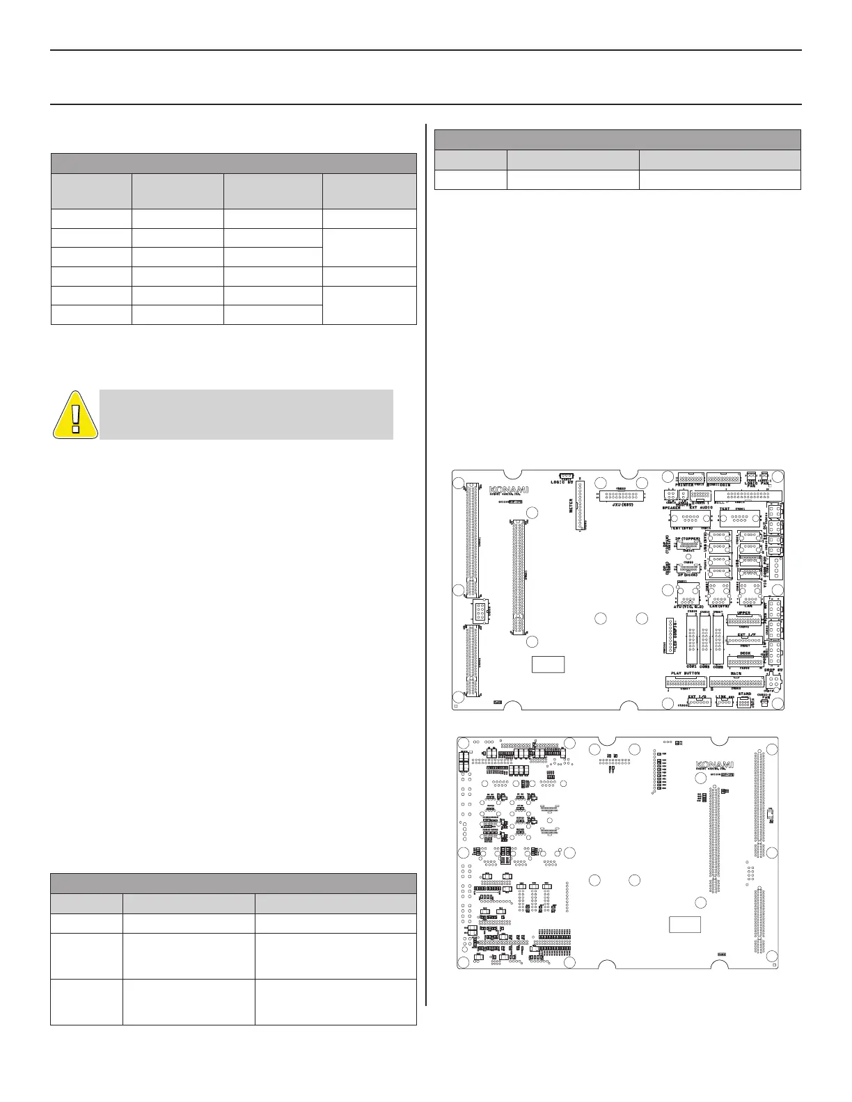
SLOT ACCOUNTING SYSTEM (SAS)
CONNECTIONS
Overview
The Slot Accounting System (SAS) communication with the
video gaming machine takes place via interface connectors
located on the Backplane Board in the Logic Unit Box and
through settings in the Konami Maintenance System (KMS)�
Connections
Under typical conditions, CNB35/COM 1 on the backplane
optic interface� CNB36 and CNB37 are used for serial
communications with conventional wiring�
KXP BACKPLANE BOARD--TOP SIDE
KXP BACKPLANE BOARD--BOTTOM SIDE
 Loading...