KRAMER: SIMPLE CREATIVE TECHNOLOGY
Connecting the TP-573 and TP-574
10
5.1 Using the RS-232 ports to control a device via a PC
To use the RS-232 ports on the TP-573 and TP-574 to control an RS-232
device, follow these connecting rules:
If the controlled device requires a CROSSED connection:
x Use a straight cable
1
from the computer to the transmitter
x Use a straight cable
1
from the receiver to the device
If the controlled device requires a STRAIGHT connection:
x Use a straight cable
1
from the computer to the transmitter
x Use a crossed cable
2
from the receiver to the device
Never use a crossed connection to the transmitter
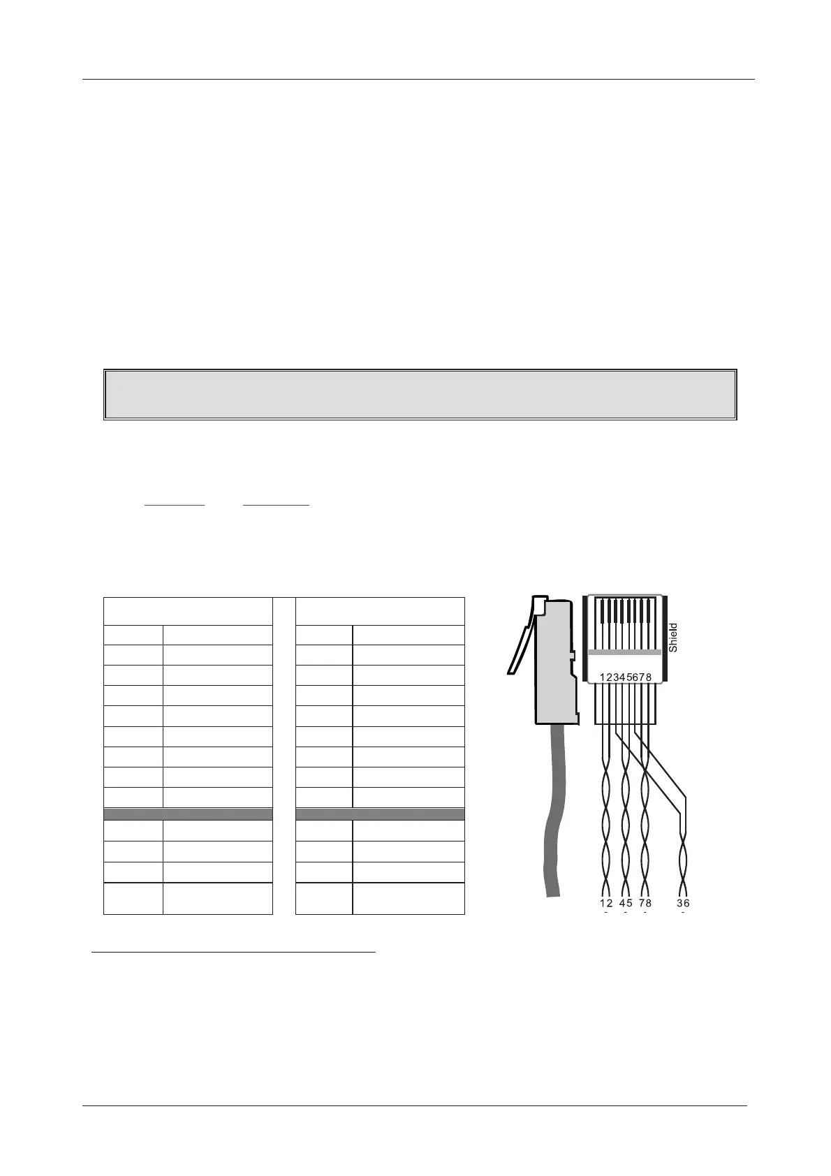
5.2 Wiring the CAT 5 LINE IN / LINE OUT RJ-45 Connectors
Table 3
and Figure 4 define the STP CAT 5 PINOUT
3
, using a straight
pin-to-pin cable with RJ-45 connectors (note, that the cable Ground
shielding must be connected / soldered to the connector shield):
Table 3: CAT 5 PINOUT
Figure 4: CAT 5 PINOUT
EIA /TIA 568A EIA /TIA 568B
PIN Wire Color PIN Wire Color
1 Green / White 1 Orange / White
2 Green 2 Orange
3 Orange / White 3 Green / White
4 Blue 4 Blue
5 Blue / White 5 Blue / White
6 Orange 6 Green
7 Brown / White 7 Brown / White
8 Brown 8 Brown
Pair 1 4 and 5 Pair 1 4 and 5
Pair 2 3 and 6 Pair 2 1 and 2
Pair 3 1 and 2 Pair 3 3 and 6
Pair 4 7 and 8 Pair 4 7 and 8
1 For a straight connection, connect pin 2 to pin 2, pin 3 to pin 3, and pin 5 to pin 5. If a shielded cable is used, connect the
shield to pin 5
2 For a crossed connection, connect pin 2 to pin 3, pin 3 to pin 2, and pin 5 to pin 5. If a shielded cable is used, connect the
shield to pin 5
3 CAT 6 or similar (heavier gauge) cabling can also be used
 Loading...