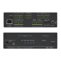
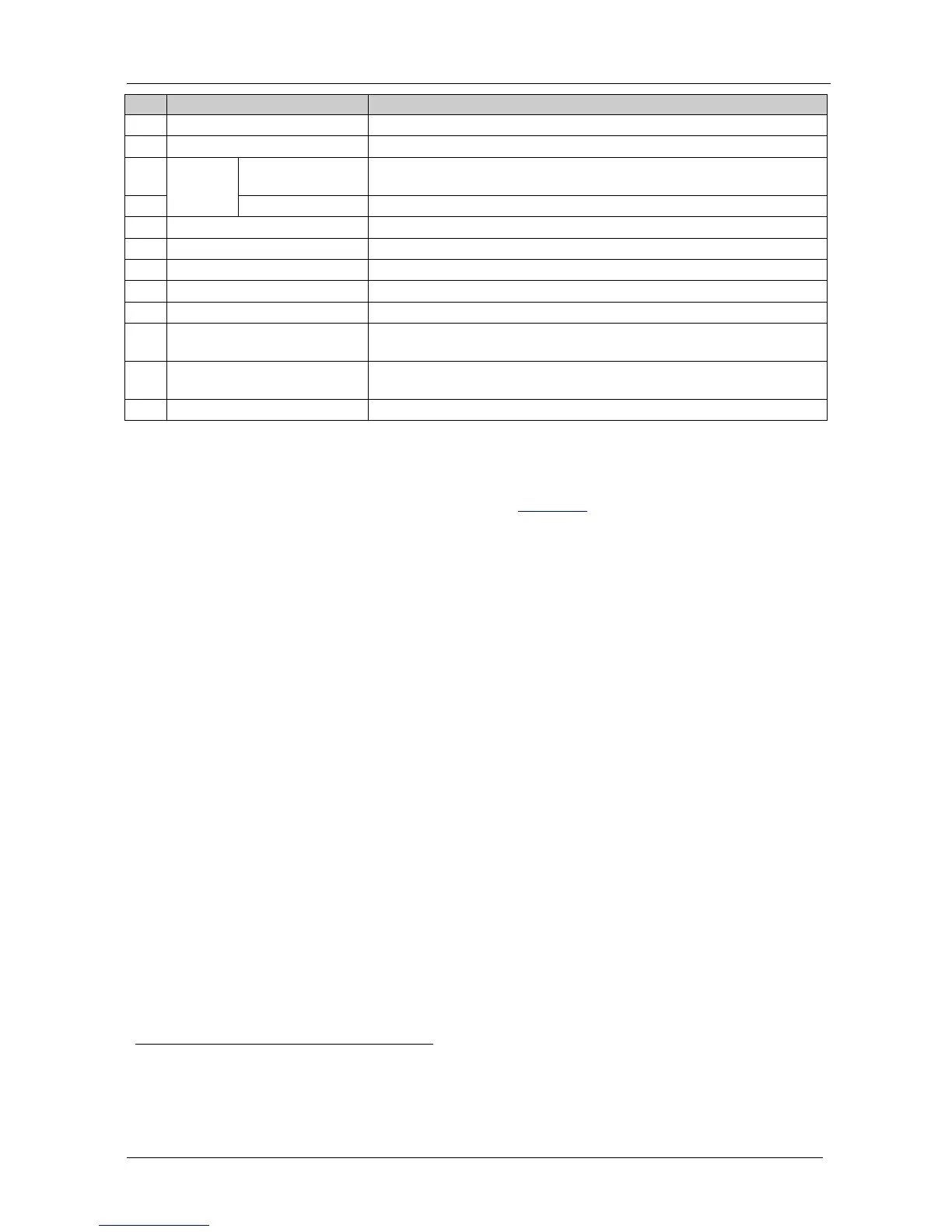
11 PROG. Switch For service use only
12 12V DC Socket 12V DC connector for powering the unit
13 IR
INPUTS
built-in receiver
and STATUS LED
Accepts IR remote commands
14 3.5mm Mini Jack Connects to an external IR receiver
15 RELAY LEDs Illuminate when a relay is active (1 to 5)
16 IR LEDs Illuminate when an IR port is active
17 NET LED Illuminates when The Ethernet link is active
18 K-NET LED Illuminates while transmitting over K-NET
19 RS-485 LED Illuminates while transmitting/receiving on an RS-485 port
20 RS-232 (Tx/Rx) LEDs Illuminate while transmitting/receiving on an RS-232 port
(1 to 2)
21 GPI/O LEDS Illuminate while transmitting/receiving on a general purpose I/O port
(1 to 2)
22 PROGRAM USB Connector Connect to a computer for unit configuration and firmware upgrading
5 Connecting the SL-10 Master Room Controller
To connect the SL-10, as the example in Figure 2 illustrates, do the following
1
1. Connect the RELAY terminal block connectors as follows:
:
Connect RELAY 1 and 2 to the projector lift
Connect RELAY 3 and 4 to the screen
Connect RELAY 5 to the lighting system
2. Connect the IR outputs as follows:
Connect an IR emitter to IR OUTPUT 1 and attach the emitter to
the DVD player
3. Connect the GPI/O ports as follows:
Connect GPI/O 1 to motion detector 1
Connect GPI/O 2 to motion detector 2
4. Connect the RS-232 ports as follows:
Connect RS-232 port 1 to the DVD player
Connect RS-232 port 2 to the projector
5. Connect the IR input as follows:
Connect IR INPUT 1 to an IR sensor (or alternatively connect IR
INPUT 1 to an external IR receiver
2
1 Switch OFF the power on each device before connecting it to your SL-10. After connecting your SL-10, switch on its power
and then switch on the power on each device
2 P/N: C- A35M/IRR two extension cables are also available: a 15 meter cable and a 20 meter cable
 Loading...