10 Related Documents
64 of 68
Calio
1157.821/04-EN
10 Related Documents
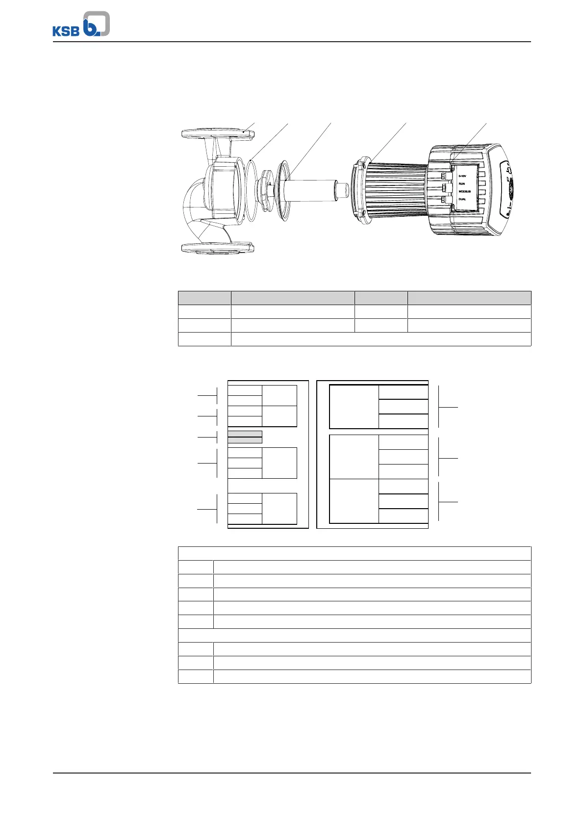
10.1 Exploded view with list of components
Fig.29: Exploded view
Table36: List of components
Part No. Description Part No. Description
01-44 Rotor 101 Pump casing
81-59 Stator 411 Joint ring
a Heat sink including frequency inverter
10.2 Wiring diagram
D+
D-
STATUS
COMRUN
NO
DUAL0-10 V
C
NC
PE
ALARM POWER
NO
C
NC
N
L
Vin
0 V
R
1
2
H
0 V
0 V
0 V
L
a1
a2
a3
a4
a5
b1
b2
b3
Fig.30: Wiring diagram of a Calio
Connections for control cables
a1 External 0-10V
a2 External start/stop
a3 Terminating resistor for Modbus cable (DIP switches)
a4 Modbus
a5 Dual-pump configuration
Connections for power supply and general fault message
b1 Power supply 1~230VAC +/- 10%, 50Hz/60Hz
b2 “In operation” message
b3 General fault message

 Loading...