2 SETUP 5
M00987-11
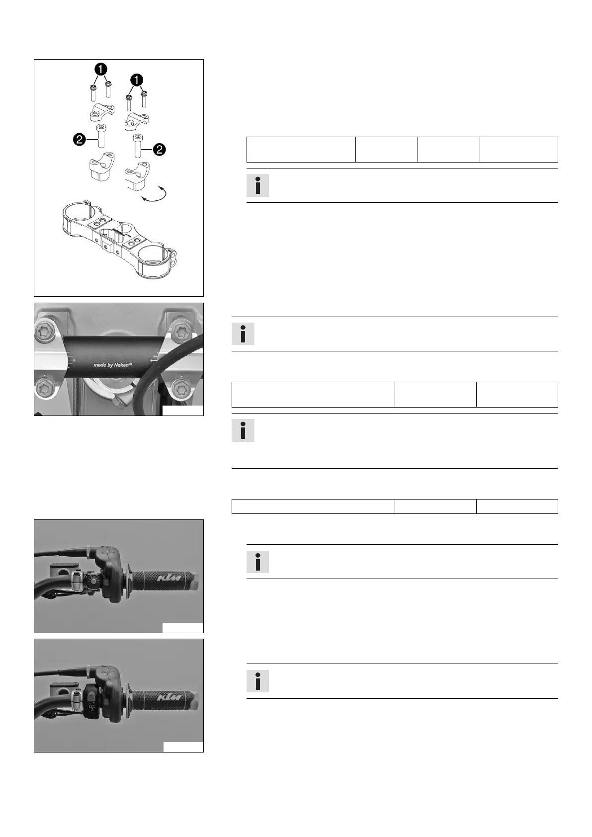
(Six Days, EXC EU/AU)
–
Remove screws
. Take off the handlebar clamps.
–
Remove screws
. Take off the handlebar supports.
– Place the handlebar supports in the required position. Mount and tighten
screws
.
Guideline
Screw, handlebar support M10 40 Nm
(29.5 lbf ft)
Loctite
®
243™
Info
Position the left and right handlebar supports evenly.
B02184-01
– Position the handlebar.
Info
Make sure the cables and wiring are positioned correctly.
– Position the handlebar clamps. Mount and tighten the screws evenly.
Guideline
Screw, handlebar clamp M8 20 Nm
(14.8 lbf ft)
Info
The markings on the handlebar should be at the center of the handlebar
clamps.
Keep the gap widths equal when tightening.
– Position the speedometer and connector board. Mount and tighten the screws.
Guideline
Remaining screws, chassis M6 10 Nm (7.4 lbf ft)
B02185-01
(XC-W, Six Days, EXC EU, 300 EXC BR)
– Position the controls on the right half of the handlebar.
Info
The routing of the cables can be seen in the figure.
V00042-01
(EXC AU)
– Position the controls on the right half of the handlebar.
Info
The routing of the cables can be seen in the figure.
 Loading...