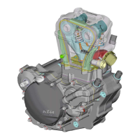
4.1 Right-hand housing half
Heat housing half to 150° C by means of hot plate.
G
ROOVED BALL BEARING OF CRANKSHAFT
1
Press old grooved ball-bearing inwards. Press in new ball bearing to the stop. The
open side of the ball cage must be towards the bottom (outside) of the case.
G
ROOVED BALL BEARING OF MAIN SHAFT
2
Press in new ball bearing from inside up to the stop.
!
CAUTION
!
D
O NOT USE FORCE WHEN PRESSING THE GROOVED BALL BEARING AGAINST THE RETAINING
BRACKET
3
TO AVOID A BENDING OF THE BRACKET, WHICH WOULD RESULT IN EXCESSIVE
AXIAL PLAY OF THE MAINSHAFT
.
G
ROOVED BALL BEARING OF COUNTERSHAFT
4
Press in new grooved ball bearing from downward to the stop. The open side of the
ball cage must be face inwards.
G
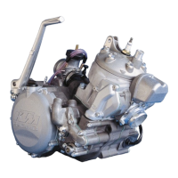
ROOVED BALL BEARING OF THE SHIFT ROLLER
5
Remove retaining screw
A
and press bearing inwards. Press in new ball bearing
from inside to the stop and secure retaining screw with Loctite 242.
N
EEDLE BUSHING OF THE SHIFT SHAFT
6
Press old needle bushing inwards, press in new needle bushing flush from the outside.
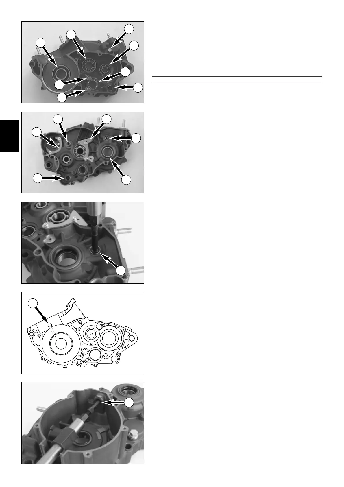
GROOVED BALL BEARING OF CENTRIFUGAL TIMER
7
The bearings usually fall out of their seat of their own accord by knocking the hou-
sinq half on a plane piece of wood when the housing has a temperature of 150° C.
If necessary use a 6 mm internal bearing extractor and guide hammer (see illustra-
tion). Press in new grooved ball bearing to the stop.
B
EARING BOLT KICKSTARTER INTERMEDIATE GEAR
8
Experience has shown that it is never necessary to replace the bearing bolt. It is not
recommended to mount a used bearing bolt in a new housing half, as it is practically
impossible to remove it without causing damage.
K
ICKSTARTER RELEASE PLATE
9
When replacing the release plate, secure the flat-head screws with Loctite 242.
C
RANKSHAFT SEAL RING
bk
Press in new shaft seal ring from the outside, with sealing lip facing inward, until
flush.
S
TOP SCREW KICKSTARTER
bl
When mounting the stop screw, it must be secured with Loctite 242. Do not forget
new copper seal ring.
R
ETAINING BRACKET
3
When replacing the retaining bracket, the two collar screws are to be secured with
Loctite 242.
Finally check clear passage of the crankshaft ball bearing lubrication bore
S
.
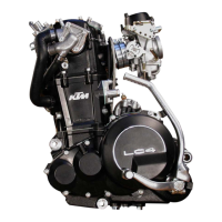
4.2 Left-hand housing half
NEEDLE BUSHINGS OF CLUTCH RELEASE
B
Remove seal ring from bore.
Knock needle bushings out of bore using a 12-16 mm extractor and guide hammer (see
illustration). Press in new needle bushings and seal ring in succession to the stop.
4
7
S
B
8
9
6
10
3
7
1
2
4
6
11
5
A
A
 Loading...