5.10 Piston and cylinder
– Before assembly, oil all parts thoroughly at the sliding points.
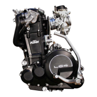
– Insert needle bearing in conrod eye, mount piston (arrow on piston head shows
direction for exhaust duct).
– Mount piston pin and wire circlips with open side showing downwards (see
sketch).
– Mount cylinder base gaskets.
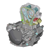
– Place piston on selfmade wooden stand and position piston ring.
– Place on preassembled cylinder, remove wooden stand and tighten cylinder
down crosswise, using two nuts.
5.11 Adjusting Dimension „X“
DIMENSION „X“ IS THE DIMENSION FROM UPPER EDGE OF PISTON TO UPPER EDGE OF CYLIN
-
DER WITH CYLINDER UNDER LOW TENSION AND PISTON IN TDC POSITION.
THE DIMENSION „X“ SHOULD BE ADJUSTED EXTREMELY CAREFULLY BY INSERTING CYLINDER
BASE GASKETS OF SUITABLE THICKNESSES
.
!
CAUTION
!
I
F THE DIMENSION
„X“ IS TOO LARGE, THE COMPRESSION RATIO WILL BE REDUCED AND THE
ENGINE LOOSES POWER
. ON THE OTHER HAND, IF THE DIMENSION „X“ IS TOO SMALL, THE
ENGINE WILL PING AND OVERHEAT
.
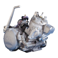
– Place slide caliper on cylinder and use feeler gauge to measure distance between
piston and slide caliper.
D
IMENSION ”X” = 0 MM + 0.1 MM (0.004 IN).
– Tighten the collar nuts at the cylinder base with 35 Nm (26 ft.lb).
5.12 Adjusting control flap (dimension “Z“)
NOTE: DIMENSION “Z“ IS THE DISTANCE FROM THE LOWER EDGE OF THE CONTROL FLAP TO
THE UPPER EDGE OF THE CYLINDER
, AS MEASURED IN THE CENTRE OF THE EXHAUST PORT.
250 : Z = 48.0
MM + 0.2 / - 0.6 MM
300 : Z = 46.0 MM + 0.2 / - 0.6 MM
380 : Z = 50.5 MM + 0.2 / - 0.6 MM
250 : Z = 1.889 IN + 0.008 IN / - 0.024 IN
300 : Z = 1.811 IN + 0.008 IN / - 0.024 IN
380 : Z = 1.988 IN + 0.008 IN / - 0.024 IN
– Undo the screws of the stop plate (left side of the cylinder)
1
and
2
and apply
Loctite 242 to the threads. Then mount both screws but do not tighten them yet.
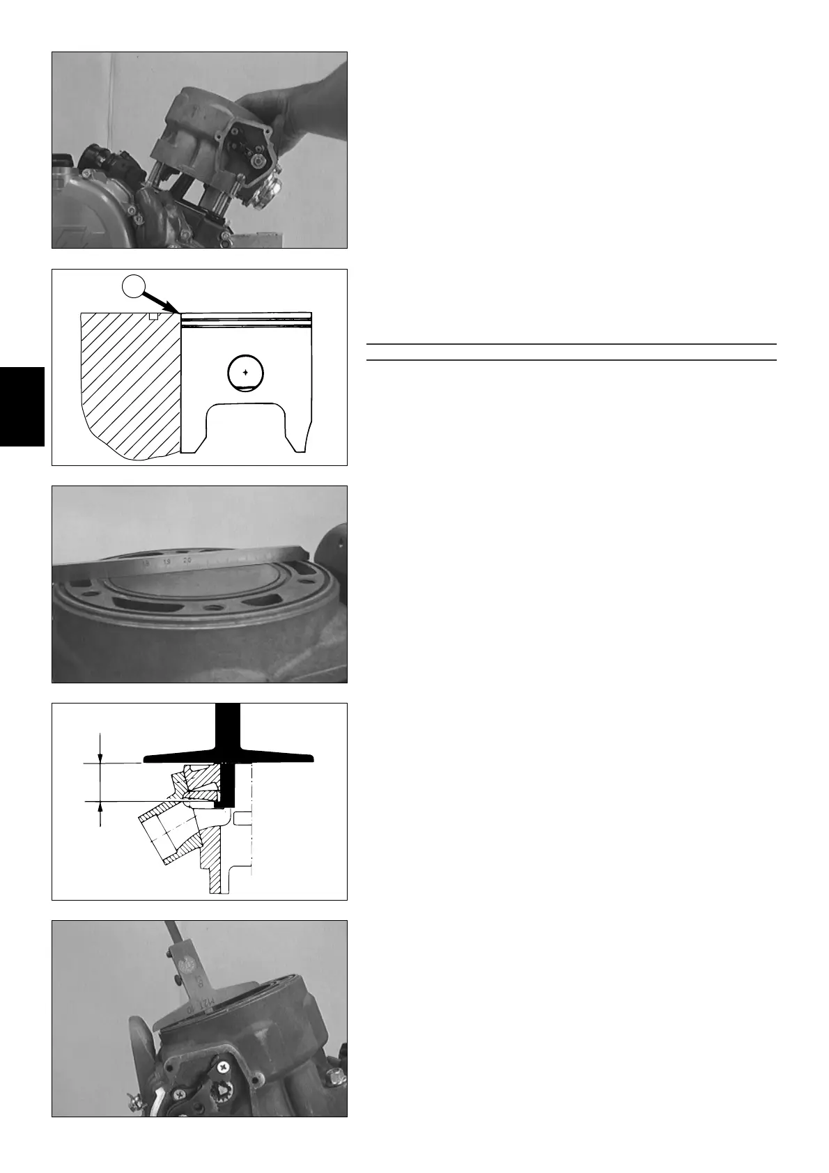
– Set preselected value on depth gauge and fix.
– Swifel control flap upwards and hold depth gauge into cylinder as shown in the
illustration.
– Control flap must rest against depth gauge.
– Allow bump plate
3
to rest against retaining bracket
4
.
5
 Loading...