6
3
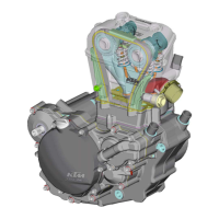
6.4 Checking the capacitor
– Discharge the capacitor by bridging the two terminals with a screwdriver and
remove.
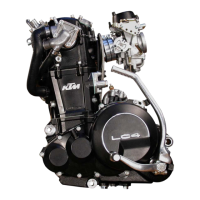
– Connect the negative pole of a 12V battery with the negative terminal of the
capacitor. The connection between the positive pole of the battery and the posi-
tive terminal of the capacitor (marked +) is made with a test lamp
3
.
– When the power circuit is closed, the test lamp must begin to light up. As capa-
citor charging increases, the brightness of the test lamp must decrease.
–
The test lamp must go out after 0,5-2 seconds (depending on the lamp capacity).
–
If the test lamp does not go out or does not light up at all, the capacitor is faulty.
!
CAUTION
!
D
ISCHARGE THE CAPACITOR BEFORE AND AFTER EACH TEST.
W
HEN INSTALLING THE CAPACITOR, MAKE SURE THAT THE TERMINALS ARE CONNECTED IN
ACCORDANCE WITH THEIR MARKINGS
(CONNECT RED/WHITE CABLE TO + TERMINAL)
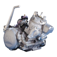
6.5 Ignition coil (SEM)
As this ignition coil uses electronic components, you are advised not to use con-
ventional measuring instruments. An accurate function test can only be carried out
on an ignition test bench.
6.6 Ignition coil (Kokusan)
– Disconnect all cables and remove the spark plug connector.
– Use an ohmmeter to measure the following values.
NOTE: THE INDICATED SETPOINT VALUES CORRESPOND TO A TEMPERATURE OF 20° C.
R
EPLACE THE IGNITION COIL IF THE MEASURED VALUES DEVIATE SIGNIFICANTLY FROM THE SET-
POINT VALUES.
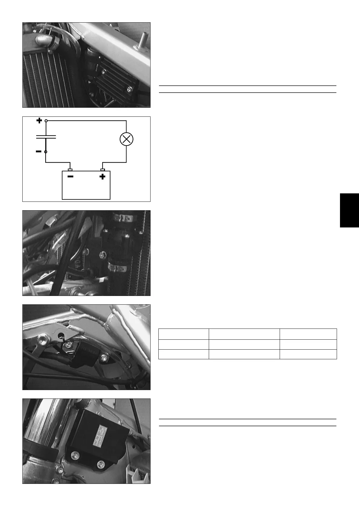
6.7 CDI unit
Check the cables and plug and socket connections of the CDI unit.
The CDI unit function can only be checked on an ignition test bench.
!
CAUTION
!
N
EVER USE A COMMERCIAL MEASURING DEVICE TO CHECK THE CDI UNIT. COMMERCIAL MEA-
SURING DEVICES CAN DESTROY HIGHLY SENSITIVE ELECTRONIC COMPONENTS.
RESISTANCE
0,425 – 0,575 Ω
10,8 – 16,2 kΩ
MEASUREMENT
primary coil
secondary coil
CABLE COLOURS
blue/white – ground
blue/white – ignition wire
3
 Loading...