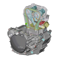
– Secure the right-hand housing half in the engine work stand.
5.1 Crankshaft
Insert crankshaft from above through grooved ball bearing and push carefully as far
as stop.
!
CAUTION
!
W
HEN PUSHING IN CRANKSHAFT, MAKE SURE CONROD IS FACING CYLINDER.
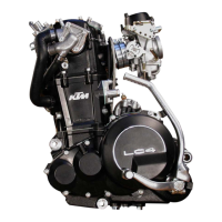
5.2 Transmission
– Introduce countershaft and stop disc approx. 2.0 mm (0.1 in) into the bearing
and hold slightly at an angle.
– Fit the mainshaft and introduce the countershaft in the bearing up to the stop.
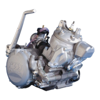
– Shift fork
1
with driving pin
A
in the middle belongs to the mainshaft.
– Mount the two other shift forks
2
at the countershaft, using the marks applied
before disassembly for better orientation.
!
CAUTION
!
U
SED SHIFT FORKS SHOULD BE MOUNTED IN THE SAME SLIDING GEAR AS BEFORE. WATCH AT
THE MARKINGS FROM DISMANTLING
.
– Hook shift forks in the sliding gears.
– Insert shift rails in shift forks (short rail towards mainshaft) and jointly pivot side-
ways (see illustration).
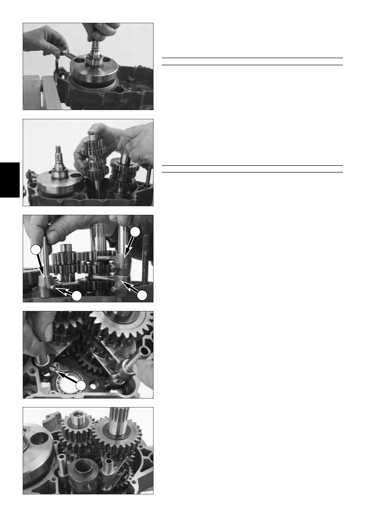
– Prior to mounting, turn shift roller in such a way that the driving pin
A
can be
hooked in at the lowest point of the middle shift groove.
– Insert shift roller in ball bearing.
– Hook in shift forks and push shift rails into bearing bores.
N
OTE: IT MUST NOW BE POSSIBLE TO GENTLY TURN GEAR SHAFTS.
5
1
A
2
2
A
 Loading...