70 HYDRAULIC UNIT
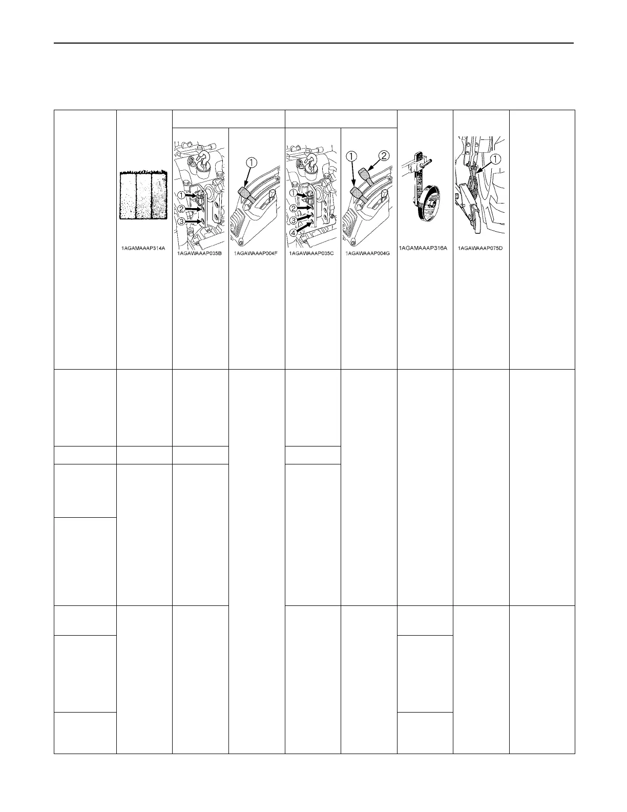
BHydraulic Control Unit Use Reference Chart
In order to handle the hydraulics properly, the operator must be familiar with the following. Though this information may not
be applicable to all types of implements and soil conditions, it is useful for general conditions.
Implement
with Position control with Draft control
Remarks
Soil
condition
Top link
mounting
holes
(1)
Position
control
lever
Top link
mounting
holes
(1)
Position
control
lever
(2)
Draft
control
lever
Gauge
wheel
(1)
Telescopic
stabilizers
Moldboard
plow
Light
soil
Medium
soil
Heavy
soil
1 or 2
2 or 3
3
Position
control
1 or 2
2 or 3
3
Draft and
Mixed
control
YES/NO Loose
Insert the
set-pin
through the
slot on the
outer tube
that align
with one of
the holes on
the inner bar.
For
implements
with gauge
wheels,
lower the
position
control lever
all way.
Disc plow --- 2 or 3 2 or 3 Place the
draft
control
lever to the
suitable
position
and set the
implement
pull with
the
position
control
lever
Harrow
(spike,
springtooth,
disc type)
--- 2 or 3 2 or 3
Sub-soiler ...
Weeder,
ridger...
--- 3 4
Position
control
YES
Tighten
Telescopic
stabilizer
should be
tight enough
to prevent
excessive
implement
movement
when
implement is
in raised
position.
Earthmover,
digger,
scraper,
manure fork,
rear
carrier.........
Hold the
draft
control
lever at the
most front
position
during
operation.
YES/NO
Mower (mid-
and rear-
mount type)
NO
 Loading...